00196962-04-BA-SX12-V2-EN.pdf - 第346页
6 Station extensions User ma nual SIPLACE SX1/SX2 6.15 Smart Pin Support F rom software version SC 706.1 SP1 Version 10/2014 346 6.15 Smart Pin Support Item no. 03089621 -xx Smart Pin Support Item no. 03087404-xx magazin…
User manual SIPLACE SX1/SX2 6 Station extensions
From software version SC 706.1 SP1 Version 10/2014 6.13 PCB alignment
345
6.13 PCB alignment
Item no. 00119677-xx PCB alignment, single conveyor
Item no. 00119678-xx PCB alignment, dual conveyor
6.13.1 Description
PCBs to be processed sometimes have a length to width ratio of 1:2 or worse. This means that
the shorter side of the PCB points in the direction of travel. During travel, such PCBs may twist
slightly and, as a result, the fiducials no longer lie within the PCB vision camera's search window.
In this case, the "PCB alignment" option ensures that these PCBs are realigned precisely at the
stopping position.
If PCBs with recesses in the direction of travel are processed, this may result in different process-
ing
positions on machines with mechanical stoppers and on machines that monitor this position with
laser light barriers. The "PCB alignment" option ensures that the PCBs are stopped at the same
position on all PCB conveyors. The "PCB alignment" option is available for both single and dual
conveyors.
The PCB is transported into the placement area until the laser light barrier triggers the stop signal
for the PCB conveyor. The lifting table with the PCB stops then moves up into a position in which
the PCB is not yet clamped and can still be moved by the conveyor belts. The two PCB stops are
level with the PCB, and the PCB supports (magnetic pins) are already in contact with the PCB.
The two conveyor belts move the PCB against the PCB stops and align them at the same time.
The lifting table then moves into its top end position, clamps the PCB and releases it from the PCB
stops so as not to affect the placement process. After the placement process, the lifting table and
PCB alignment are lowered and the PCB is moved on.
6.14 Siemens interface
Item no. 00116808-xx SIPLACE interface
The conveyor interface on the placement machines from the SX and X-Series is configured to the
SMEMA standard. It is, however, still possible to use this interface in accordance with the Siemens
standard. This is a significant benefit when an X-Series machine is to be integrated into older SI-
PLACE lines, in which case it would not be necessary to retrofit the older machines to conform to
the SMEMA standard.
Simply configure the conveyor interface of the SX-Series and X-Series machines to the Siemens
standard and connect the machines using the associated interface cable.
6 Station extensions User manual SIPLACE SX1/SX2
6.15 Smart Pin Support From software version SC 706.1 SP1 Version 10/2014
346
6.15 Smart Pin Support
Item no. 03089621-xx Smart Pin Support
Item no. 03087404-xx magazine SPS L10 assembly
Item no. 03087508-xx magazine SPS Q10 assembly
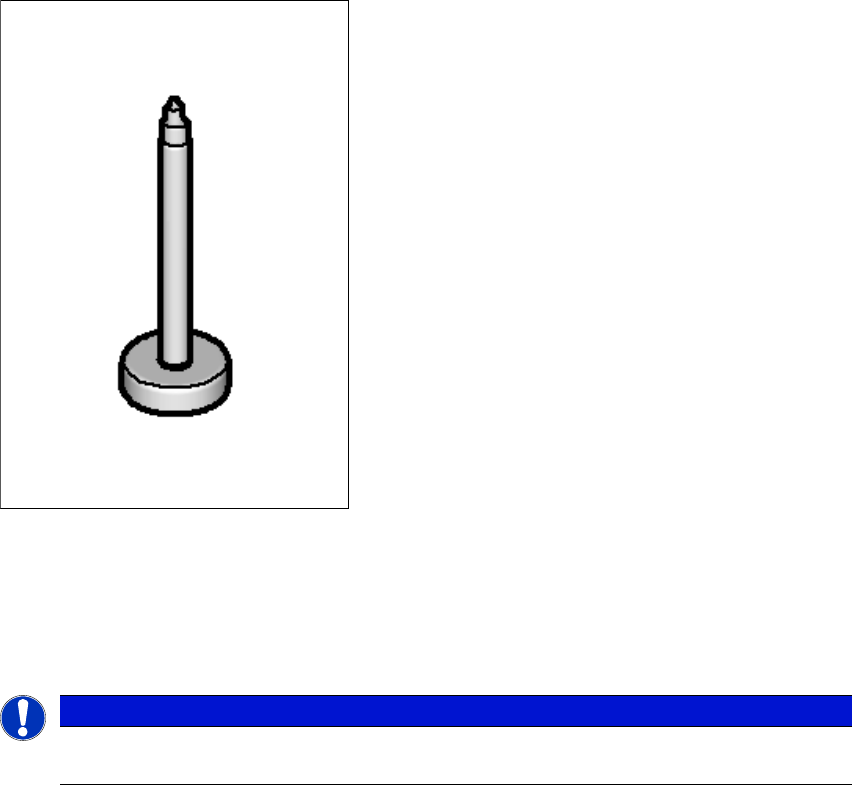
Wide boards tend to deflect during placement such that, under certain circumstances, the compo-
nents can no longer be placed with the desired accuracy. Highly curved PCBs also affect the
placement accuracy. This problem can be easily rectified by fitting support pins on the lifting table.
6
Fig. 6.15 - 1 Support pin
The support pins are automatically placed on the lifting table with the help of the Smart Pin Sup-
port option. A gripper unit is used to pick the support pins up from special magazines and place
them in the prescribed positions.
6
PLEASE NOTE
For a detailed description, see the "Smart Pin Support User Manual", German+English
[item no. 00197001-xx]
User manual SIPLACE SX1/SX2 6 Station extensions
From software version SC 706.1 SP1 Version 10/2014 6.15 Smart Pin Support
347
6
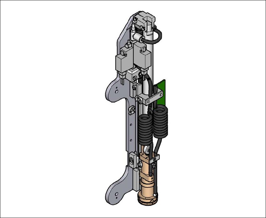
Fig. 6.15 - 2 Gripper unit for Smart Pin Support
The gripper unit is fitted to the gantry. This gripper unit picks the support pins up from the pre-
scribed magazine and positions them on the lifting table. The positions of the support pins in the
machine can be defined for each board side, in the SIPLACE Pro Board Editor.
There are two different magazines available for automatic changeover of max. 10 support pins in
the various machine configurations. These magazines are fixed to a magazine holder and are fit-
ted to the component trolley COT insert.
– Smart Pin Support - magazine type Q10 [item no. 03087404-xx]
– Smart Pin Support - magazine type L10 [item no. 03087508-xx]