00196962-04-BA-SX12-V2-EN.pdf - 第76页
2 Operational safety User manual SIPLACE SX1/SX2 2.7 Safety features From software version SC 706.1 SP1 Version 10/2014 76 2 Fig. 2.7 - 8 EMERGENCY STOP loop for SIPLACE SX1/SX2 S tart button pressed. No No Ye s No No Ye…
User manual SIPLACE SX1/SX2 2 Operational safety
From software version SC 706.1 SP1 Version 10/2014 2.7 Safety features
75
2.7.4.2 Signaling circuit structure
The following modules in the signaling circuit are queried individually:
– The protective cover switches
– Bumper monitoring of Y axis
– Signaling contacts on the component trolley
– EMERGENCY STOP button
All the signaling contacts are closed when the machine is on standby. If a protective cover, for ex-
ample, is raised, the associated signaling contact opens. This change of state is signaled to the
control computer via the CAN bus. An error message to this effect appears on the user interface.
2.7.4.3 Description of the functions of the EMERGENCY STOP loops
The following conditions must be fulfilled in order to start and operate the machine:
– All component trolleys must be docked in and connected.
– All protective covers must be closed.
– All stopper bumpers for the Y axis must be fitted.
– Both emergency stop buttons must be released.
– The minimum operating pressure must have been reached.
– The software release ("Control ON") must be enabled, so that the start signal from the "Start"
button can switch on the SSK protective contactor combination.
– 24V- are made available by the output of the AC/DC converter to the start button and the pro-
tective contactor combination (SSK).
If one of the start buttons is now pressed, the protective contactor combination SSK K3 will switch
and the machine will be ready for operation.
2 Operational safety User manual SIPLACE SX1/SX2
2.7 Safety features From software version SC 706.1 SP1 Version 10/2014
76
2
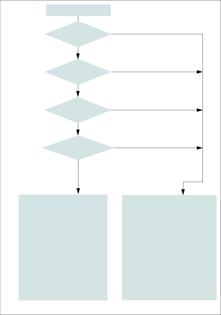
Fig. 2.7 - 8 EMERGENCY STOP loop for SIPLACE SX1/SX2
Start button pressed.
No
No
Yes
No
No
Yes
Yes
2
Active
SSK
a
No
Voltage
Y axis 0 V-
X axis 0 V-
Star axis 0 V-
DP axis 42 V-
Z axis (C&P, TH) 42 V-
Z axis (CPP) 0 V-
Active
PCB conveyor No
Lifting table No
PCB clamping No
Width adjustment No
Tape cutter No
Component trolley feeding device Yes
a) SSK protective contactor combination K3
Yes
Compressed
air min. 0.5 MPa
(5.0 bar)?
EMERGENCY STOP button
pressed?
- Protective cover open?
- Is Y axis bumper missing?
Component trolley
EMERGENCY STOP circuit
interrupted?
2
Active
SSK
a
Yes
Voltage
Y axis 260 V-
X axis 260 V-
Star axis 150 V-
DP axis 42 V-
Z axis (C&P, TH) 42 V-
Z axis (CPP) 150 V-
Active
PCB conveyor Yes
Lifting table Yes
PCB clamping Yes
Width adjustment Yes
Tape cutter. Yes
Component trolley feeding device Yes
User manual SIPLACE SX1/SX2 2 Operational safety
From software version SC 706.1 SP1 Version 10/2014 2.7 Safety features
77
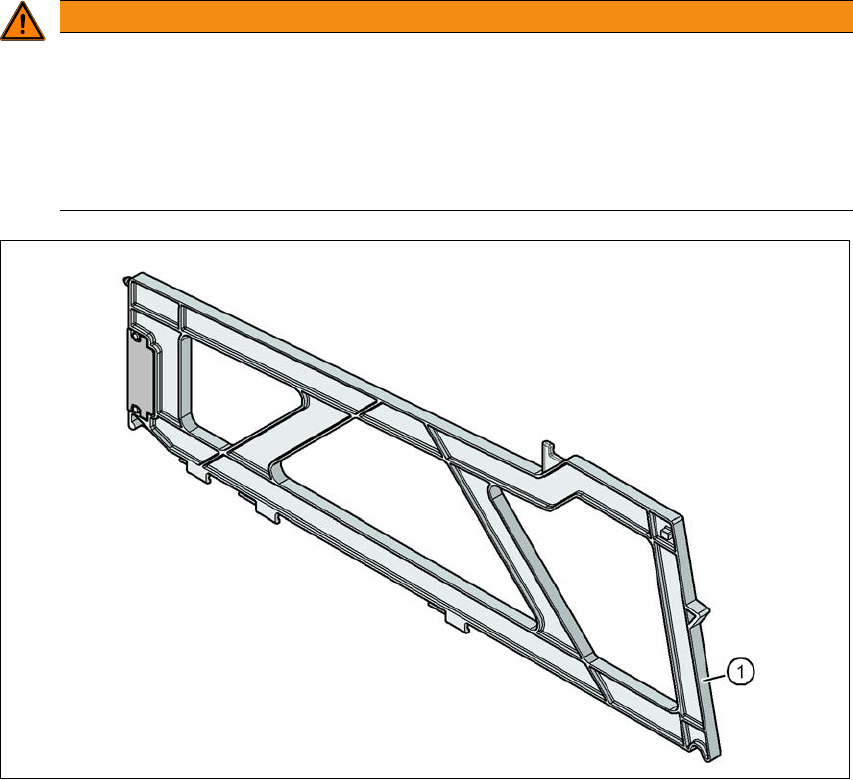
2.7.5 Hand guard
2.7.5.1 Hand guard at the locations
2
Fig. 2.7 - 9 Hand guard on the component trolley locations
2
(1) Dummy feeder SIPLACE X, item no. 00141226-xx
WARNING
Operational
Operational safety by occupying every second location!
The operational safety of the component trolley in the SIPLACE SX1/SX2 is ensured if at
least every second free location is occupied with a feeder module or hand guard (dummy
feeder).
Even when configuring a holder for waffle pack trays, secure every second location
with a hand guard.