00196962-04-BA-SX12-V2-EN.pdf - 第82页
2 Operational safety User manual SIPLACE SX1/SX2 2.9 Disabling the compressed air supply and discharging the pressure From software version SC 706.1 SP1 Version 10/2014 82 2 Fig. 2.9 - 1 Compressed air unit on the machin…
User manual SIPLACE SX1/SX2 2 Operational safety
From software version SC 706.1 SP1 Version 10/2014 2.9 Disabling the compressed air supply and discharging the pressure
81
2
2.9 Disabling the compressed air supply and discharging
the pressure
The compressed air working pressure of the machine is set to 0.50 ± 0.025 MPa (5.0 ± 0.25 bar).
The position of the compressed air unit is shown at item 1 in fig. 2.9 - 1
, page 82 ) The supply of
compressed air to the machine can be interrupted with the shutoff valve (item 2 in fig. 2.9 - 1
, page
82
).
Use the machine key to release the cover lock.
Lift the cover (see fig. 2.9 - 1, page 82 ).
Turn the lever of the shutoff valve (item 1 of fig. 2.9 - 1, page 82) from the vertical to the hor-
izontal position.
Monitor the operating pressure manometer (item 5 in fig. 2.9 - 1, page 82 ). When the machine
is switched on, the pressure discharges to 0 MPa (0 bar) within 1 minute.
2
CAUTION
Data loss!
To avoid losing data, assess the following criteria before switching off your machine (apart
from in emergencies):
– Has the machine finished transmitting machine, setup and panel data?
– Has the machine finished processing the PCB?
– Has the machine completed the run-up phase?
CAUTION
Interruption to compressed air supply!
When the machine is switched on, do not use the stop valve to interrupt the com-
pressed air supply for more than 30 minutes.
If you need to shut off the pneumatic system for longer in order to carry out preventive
maintenance or servicing work, you must switch the machine off at the main switch
and disconnect it from the power supply.
2 Operational safety User manual SIPLACE SX1/SX2
2.9 Disabling the compressed air supply and discharging the pressure From software version SC 706.1 SP1 Version 10/2014
82
2
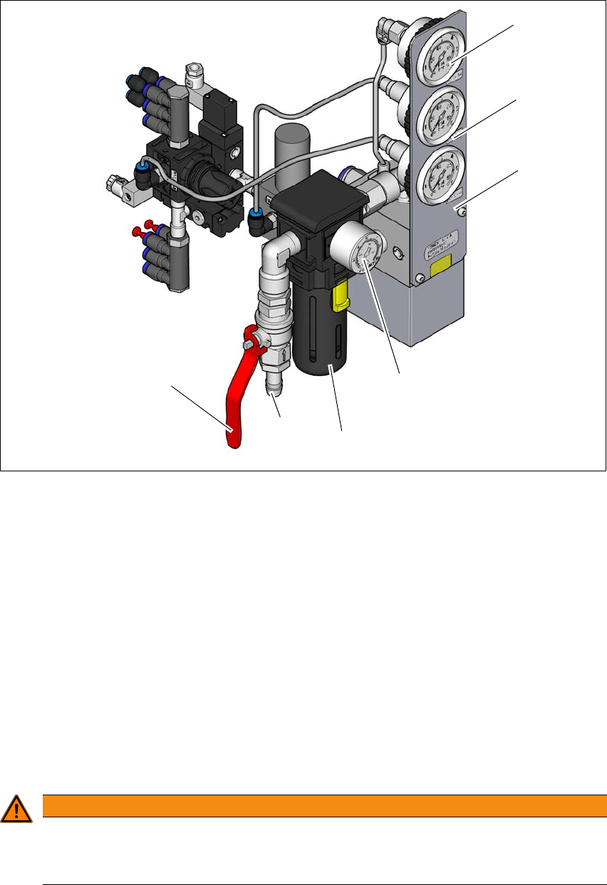
Fig. 2.9 - 1 Compressed air unit on the machine
(1) Manometer for supply pressure of gantries 1 and 2
Target pressure: 0.46 ± 0.01 MPa, 4.6 ± 0.1 bar (display range 0 - 0.6 MPa, 0 - 6 bar)
(2) Manometer for the machine component supply pressure
Target pressure: 0.5 ± 0.025 MPa, 4.5 ± 0.25 bar (display range 0 - 0.6 MPa, 0 - 6 bar)
(3) Manometer for the bulkcase feeder module supply pressure
Target pressure: 0.25 ± 0.05 MPa, 2.5 ± 0.5 bar (display range: 0 - 0.6 MPa, 0 - 6 bar)
(4) Manometer for inlet pressure
Target pressure: 0.5 - 1.0 MPa, 5.0 - 10.0 bar (display range: 0 - 1.0 MPa, 0 - 10 bar)
(5) Compressed air filter
(6) Compressed air connection
(7) Stop valve in the "OPEN" position
2
WARNING
Risk of injuries!
Risk of injuries from pressurized compressed air lines.
NEVER detach compressed air lines while they are still pressurized.
(6)
(1)
(2)
(3)
(4)
(5)
(7)
User manual SIPLACE SX1/SX2 2 Operational safety
From software version SC 706.1 SP1 Version 10/2014 2.10 Energy state of the machine after switching off at the main power switch
83
2.10 Energy state of the machine after switching off at the
main power switch
2
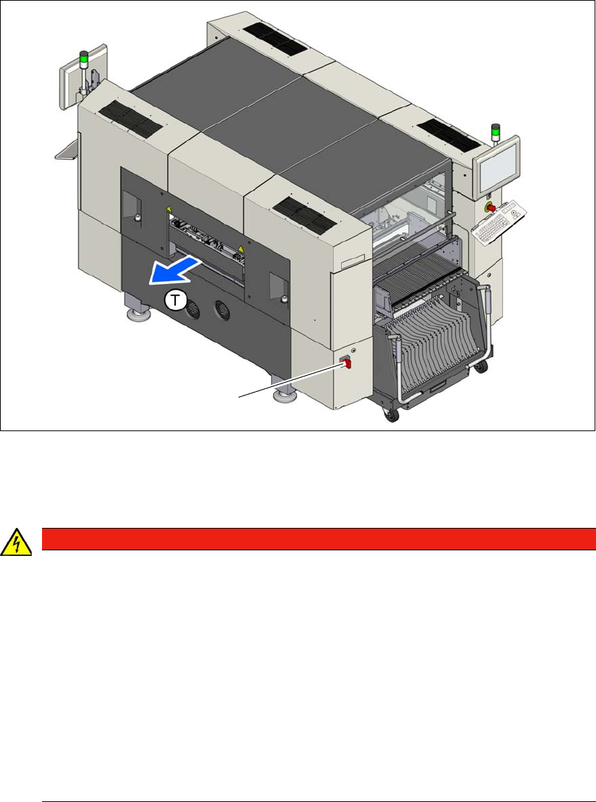
Fig. 2.10 - 1 Position of the power supply on the machine
2
2
(1) Main switch
DANGER
Dangerous voltage levels!
The machine is supplied with 3 x 200 V~, 3 x 208 V~, 3 x 220 V~, 3 x 230 V~, 3 x 380 V~,
3 x 400 V~ or 3 x 415 V~ ± 5 %, 50/60 Hz mains voltage. This means that some parts of
the system carry potentially lethal voltages - even when switched off at the main power
switch.
Incorrect handling of this machine can therefore result in death or severe injury or consid-
erable damage to equipment.
Always follow the applicable accident prevention and DIN regulations (particularly EN
60204, part 1 or IEC 60204, part 1) and the applicable regulations in your own coun-
try.
The covers over the power supply unit may ONLY be opened by appropriately quali-
fied and trained personnel.
(1)