00196962-04-BA-SX12-V2-EN.pdf - 第85页
User manual SIPLACE SX1/SX2 2 Operational safety From software version SC 706.1 SP1 Version 10/2014 2.10 Energy state of the machine after switching off at the main power switch 85 2 Fig. 2.10 - 3 Power supply unit, side…
2 Operational safety User manual SIPLACE SX1/SX2
2.10 Energy state of the machine after switching off at the main power switch From software version SC 706.1 SP1 Version 10/2014
84
2.10.1 Machine switched off at the main switch, but still connected
2
2
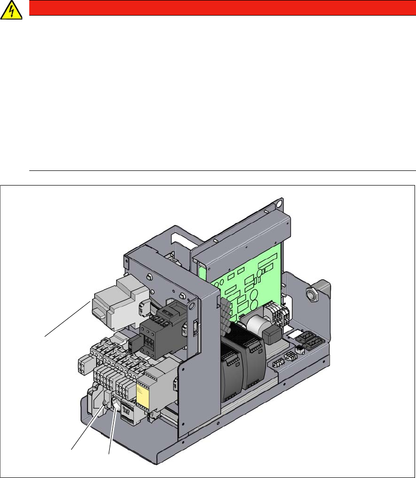
Fig. 2.10 - 2 Power supply unit, front view
(1) Service socket (X98)
(2) Fuse for service socket (F1)
(3) Main switch (Q1)
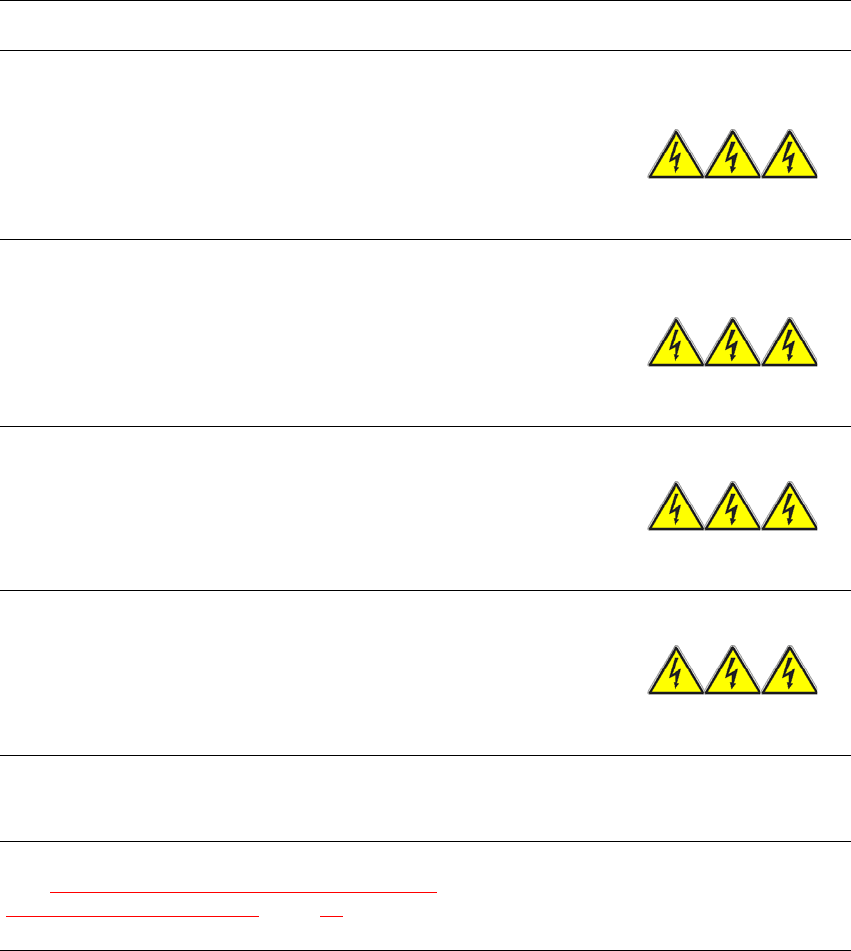
DANGER
Lethal voltages!
Incorrect handling of the machine can therefore result in death or severe injury or consid-
erable damage to equipment.
The following components still carry potentially lethal voltages even if the main power
switch is switched off:
– Mains connection terminals in the transformer unit L1, L2 and L3 of main switch Q1
– Service socket X98
– F1 automatic circuit breaker for the service socket
– The color of all individual wires, which still carry potentially lethal voltages even if the
main power switch is switched off, is brown.
(3)
(1)
(2)
User manual SIPLACE SX1/SX2 2 Operational safety
From software version SC 706.1 SP1 Version 10/2014 2.10 Energy state of the machine after switching off at the main power switch
85
2
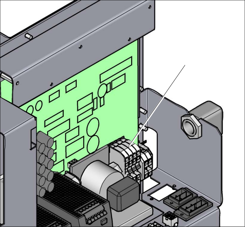
Fig. 2.10 - 3 Power supply unit, side view
(1) Terminals (X99) for the power supply cable
(1)
2 Operational safety User manual SIPLACE SX1/SX2
2.10 Energy state of the machine after switching off at the main power switch From software version SC 706.1 SP1 Version 10/2014
86
The following table specifies the voltages of modules when the machine is switched off at the main
switch, but still connected to the mains supply.
2
2.10.2 Machine switched off at the main power switch and disconnected
The machine is unpowered, apart from slight residual voltages in the power supply unit.
Module Voltage
Terminal panel X99
terminals L1, L2, L3
3 x 200 V~
3 x 208 V~
3 x 220 V~
3 x 230 V~
3 x 380 V~
3 x 400 V~
3 x 415 V~
Service socket X98
115 V~
120 V~
130 V~
156 V~
220 V~
230 V~
240 V~
Automatic circuit breaker F1
115 VAC
120 VAC
130 VAC
220 VAC
230 VAC
240 VAC
Main switch Q1
Terminals L1, L2, L3
3 x 200 VAC
3 x 208 VAC
3 x 230 VAC
3 x 380 VAC
3 x 400 VAC
3 x 415 VAC
Main switch Q1
terminals to transformer unit T1, T2, T3
0 VAC
Power supply unit
(see Residual voltages and discharge times after
switching off the main switch, page 80)