SYS-CP842-1.1E.pdf - 第107页
3.Machine System SYS-CP842-1.1E 98 CP-842E / CP-842ME System Reference Pickup Data Editing Sc reen Pickup data can be edited from this scr een. Push the START button. FUJI Error Operator JOG:X Y CAM Servo Count GEM CCD M…

SYS-CP842-1.1E 3.Machine System
CP-842E / CP-842ME System Reference 97
Problem
Panel's BS-mark pattern size differs from
wire frame's size.
BS-mark reading result differs from panel's
BS-marks.
BS-mark reading result differs from panel's
BS-marks.
Editing Operation
If the BS-mark size is incorrect, edit sizes
X and Y.
If the BS-mark reading threshold value is
unsuitable, edit the brightness.
If the BS-mark reading color is incorrect,
edit the color.
T003E
3.Machine System SYS-CP842-1.1E
98 CP-842E / CP-842ME System Reference
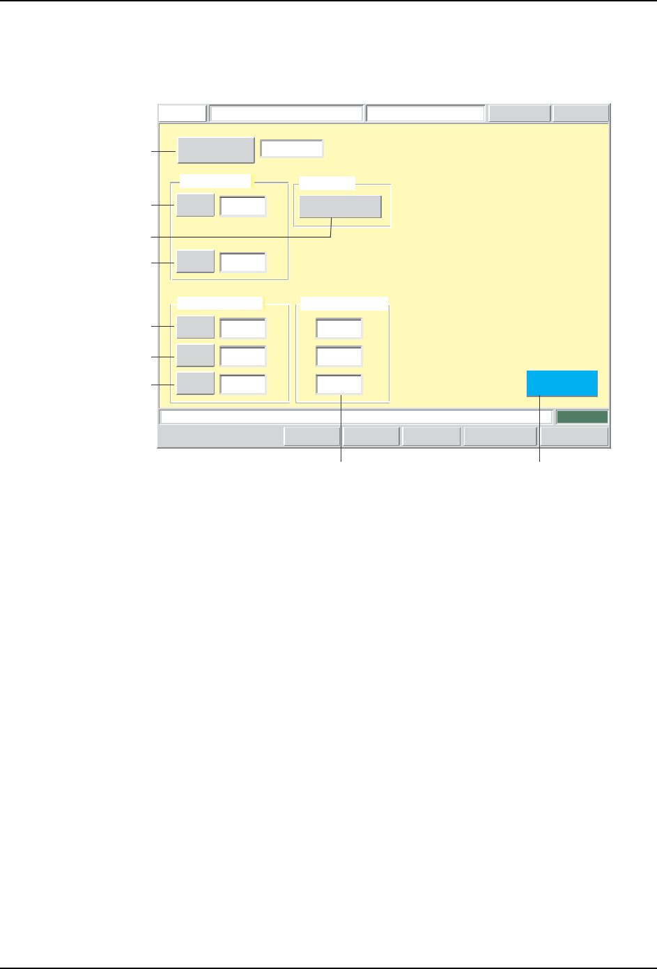
Pickup Data Editing Screen
Pickup data can be edited from this screen.
Push the START button.
FUJI
ErrorOperator
JOG:X Y CAM
Servo Count
GEMCCD Monitor
Pickup Data EditorFUJI_CP7_2001
Front
Close
X
Z
0.0000
0.0000
Pickup Offset
[mm]
[mm]
X
Y
Q
0.6000
0.8000
30.0000
Pickup Tolerance
[mm]
[mm]
[deg]
123
Detailed Settings
Pickup Data
Sequence Number
Set Switch
Vision Processing Result
X:
Y:
Q:
[mm]
[mm]
[deg]
0.2620
0.1870
2.1639
CP7S2016E
A
B
C
G
D
E
F
H1
SYS-CP842-1.1E 3.Machine System
CP-842E / CP-842ME System Reference 99
Screen Button Explanations
Display Item Explanations
1. [Vision Processing Result]:Displays the part camera vision processing result.
Editing Operations
The following editing operations can be performed at this screen.
A. [Sequence No.]: Switches to the sequence search screen.
B. [X] (Pickup position offset): Changes the offset (PTPCRPOX) from the feeder
cavity’s center pickup point. This offset is specified in
the production program’s part shape data
(CARRING).
C. [Z] (Pickup position offset): Changes the pickup height offset (PTPCRPOZ) (set
according to part packaging type) which is specified in
the production program’s part shape data
(CARRING).
D.[X] (Pickup tolerance): Changes the pickup position X-direction tolerance
(PTPTLPX) which is specified in the production
program’s part shape data (TOLEINF).
E. [Y] (Pickup tolerance): Changes the pickup position X-direction tolerance
(PTPTLPY) which is specified in the production
program’s part shape data (TOLEINF).
F. [Q] (Pickup tolerance): Changes the pickup position angle tolerance
(PTPTLPQ) which is specified in the production
program’s part shape data (TOLEINF).
G. [Detailed Settings]: Switches to the pickup data “detailed settings” screen.
H. [Close]: Returns to the production program editing screen.
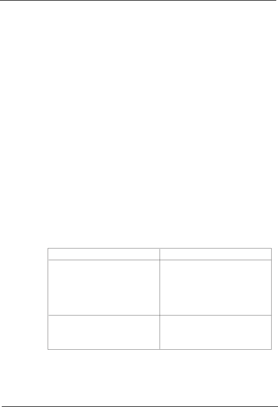
Problem
A vision processing error (pickup error) or
a tolerance error occurs during test
placement.
A tolerance error occurs during test
placement.
Editing Operation
Use the vision commands to check the
vision processing result. Edit the pickup
position offset X, Y values if the following
conditions exist: No part has been picked up.
The picked up part is badly out of position.
The part has been picked up standing on
end.
Use the vision commands to check the
vision processing result. If the picked up part
is not badly out of position, edit the pickup
tolerance X, Y, Q values.
T004E