00198051-01_IM_SetupCenter_8.0_EN.pdf - 第88页
Docking Station Installation Data Connection with PC-CAN Card 7.3.2 Connection Examples with PC-CAN Card 88 Installation Manual SIPLACE Setup Center 8.0 7.3.2 7 . 3 . 2 C o n n e c t io n E x a m p le s w it h P C - C A …
Docking Station Installation
7.3.1 Installing the CAN Card in the PC Data Connection with PC-CAN Card
Installation Manual SIPLACE Setup Center 8.0 87
7.3
7.3 Data Connection with PC-CAN Card
Data Connection with PC-CAN Card
7.3.1
7.3.1 Installing the CAN Card in the PC
Installing the CAN Card in the PC
The data connection between the Setup Center PC, on which the Setup Center software is to be in
-
stalled, and the docking station is realized via a CAN Bus. This requires installation of a CAN card in the
Setup Center Computer. This CAN card is included in the delivery of docking station (optional).
► Open the Setup Center Computer housing according to the manufacturer's instructions.
► Select a free PCI slot in your Setup Center Computer for installing the CAN card.
► Plug the CAN card into the selected PCI slot.
► Close the Setup Center Computer housing according to the manufacturer's instructions.
► The drivers for the CAN card are contained on the Setup Center software installation CD. These
need to be installed separately. For a detailed description, please see Section " Installing the CAN
Bus driver and API".
NOTICE
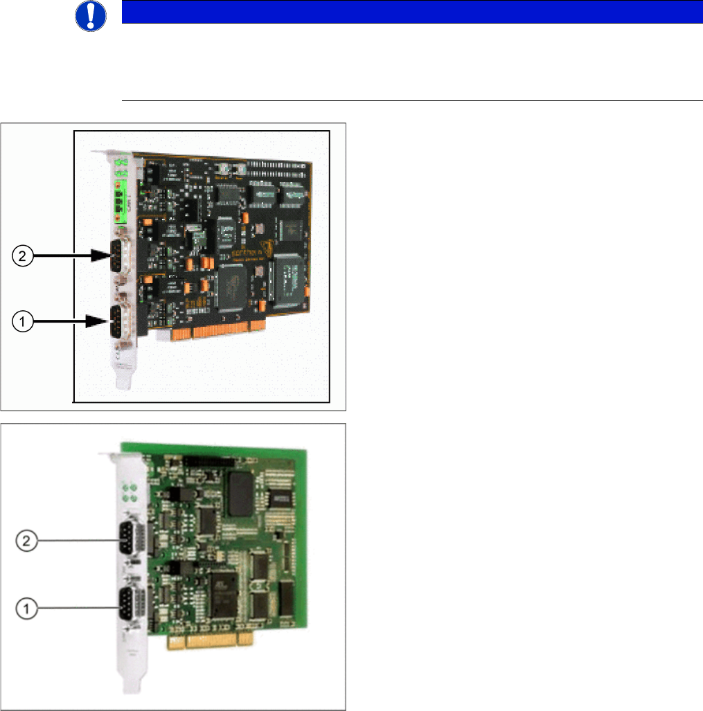
There are two different models of CAN cards available:
The CAN card Power CAN PCI supports only 32 bit operating systems, the newer version Pow
-
er CAN PCI COM 168 V2 supports 32 bit as well 64 bit operating systems. The driver and API
installation package is supporting both CAN card models.
CAN Card - Power CAN PCI
1. Bus 1
2. Bus 2
CAN Card - Power CAN PCI COM 168 V2
1. Bus 1
2. Bus 2
Docking Station Installation
Data Connection with PC-CAN Card 7.3.2 Connection Examples with PC-CAN Card
88 Installation Manual SIPLACE Setup Center 8.0
7.3.2
7.3.2 Connection Examples with PC-CAN Card
Connection Examples with PC-CAN Card
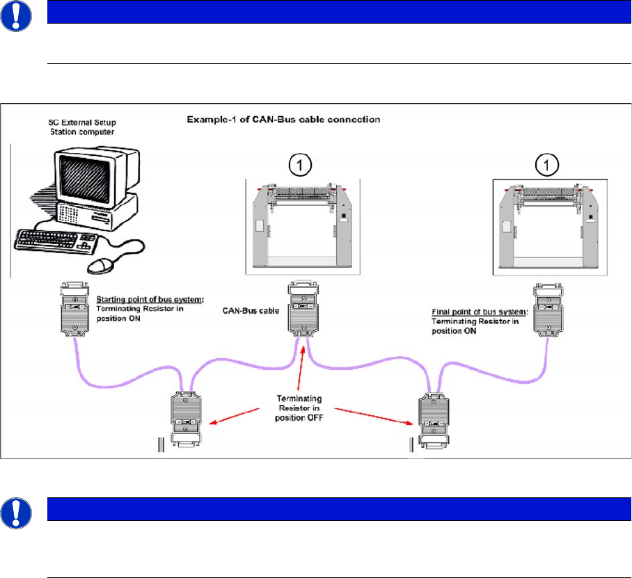
Connection Example 1
1. Docking Station X or SX
NOTICE
The first and the last terminating resistor must always be switched ON and the other switched
OFF independent of the number of docking stations.
NOTICE
The integrated terminal resistor can be connected and simultaneously connects / disconnects
the outgoing bus cable when deactivating / activating. This allows an easy start up of the bus
system one segment at a time.
Docking Station Installation
7.3.2 Connection Examples with PC-CAN Card Data Connection with PC-CAN Card
Installation Manual SIPLACE Setup Center 8.0 89
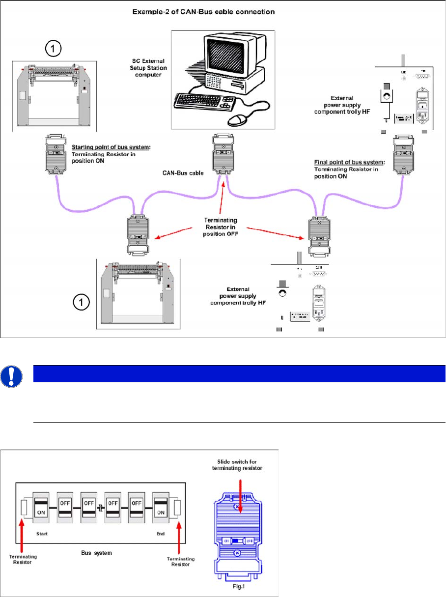
Connection Example 2
1. Docking Station X or SX
Connection Example 1 and 2
NOTICE
The integrated terminal resistor can be connected and simultaneously connects / disconnects
the outgoing bus cable when deactivating / activating. This allows an easy start up of the bus
system one segment at a time.