00198576-01_JG_Nozzles_E-by-SIPLACE_EN.pdf - 第13页
1 - 9 www.e-by-siplace.com Correct Assignment of Nozzle – Component for SIPLACE To prevent any detection problems with small structures, the component must be in the focus range (area of focus) of the camera. The focus r…
1 - 8
www.e-by-siplace.com
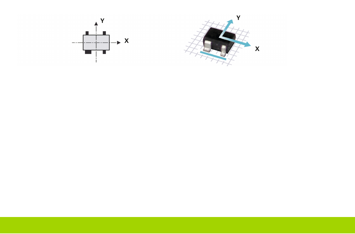
Rule 4: If the component has a special feature, such as a wider lead, this special feature will be at the bottom.
Rule 1 has top priority, followed by rules 2, 3 and 4.
1 - 9
www.e-by-siplace.com
Correct Assignment of Nozzle – Component for SIPLACE
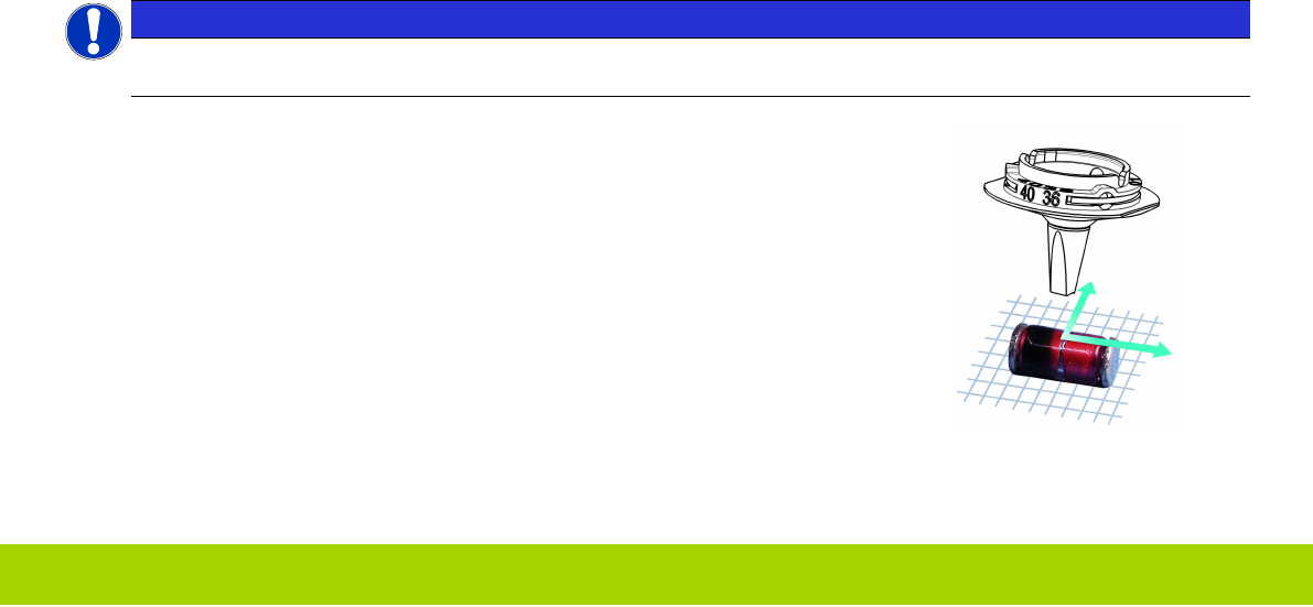
To prevent any detection problems with small structures, the component must be in the focus range (area of focus) of the
camera.
The focus range of the SIPLACE CP14 camera is between 9.4 and 11.4 mm (i.e. 10.4 +/– 1mm).
The focus range of the SIPLACE CP6/12 camera is between 15.4 +/– 2mm).
The Twin head positions the bottom side of the component into the correct focus plane of the camera if the nozzle length
and the component height are programmed correctly.
NOTICE
When selecting the correct nozzle for a component, check whether the total value of nozzle length plus compo-
nent height is within this range.
Example:
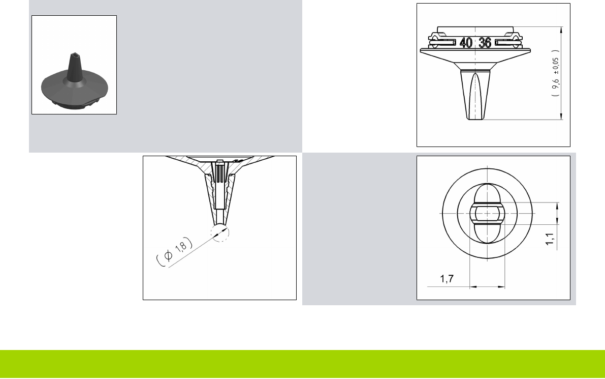
Nozzle length L = 9.600 mm
Component height H = 1.300 mm
Immersion depth = 0.200 mm
Overall height = nozzle length + component height - immersion depth = 10.700mm
1 - 10
www.e-by-siplace.com
Nozzle Descriptions
Example:
L = 9.600 mm
r
tip
= 0.900 mm
Tip: 1.200 x 0.900 mm (LxW)
L shows the nozzle
length from the base
to the tip.
r
tip
shows the radius of
the nozzle tip for cyl-
indrical components.
Example:
r
tip
= Ø 1.800 mm / 2
= 0.900 mm
Tip shows the length
and width or the dia-
meter of the nozzle tip
(outer dimensions).