20121120111955_KY8030_2_Maintenance_Manual_Eng_ver1 - 第25页
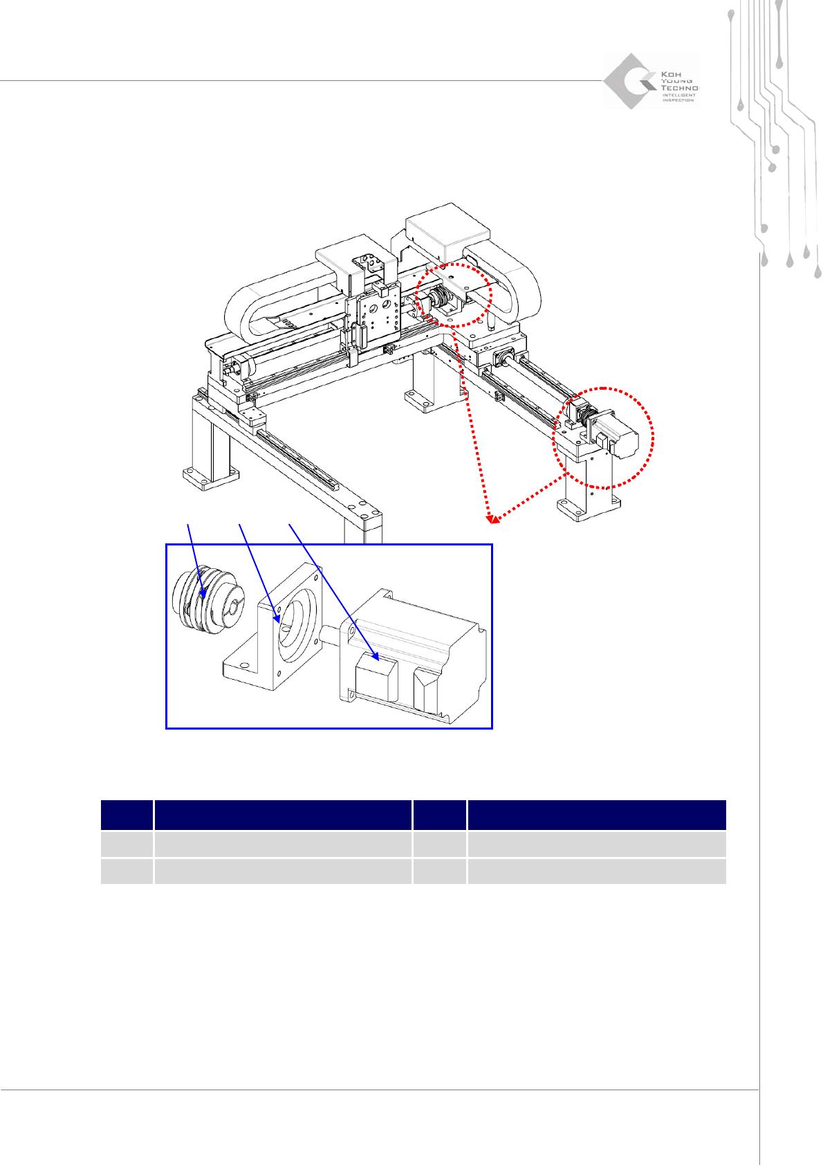
Maintenance Manual | 25 1.2.2. C OUPLING AND M OTOR C HANGE Figure 1-3. Axis Coupling and Motor Item Description Item Description 1 Coupling 3 Servo Motor 2 Motor Bracket 1. Cut the power/the air s upply and …
24 | KY-8030 2
3DSolderPasteInspectionSystem
Version 1.0
KOH YOUNG TECHNOLOGY INC.
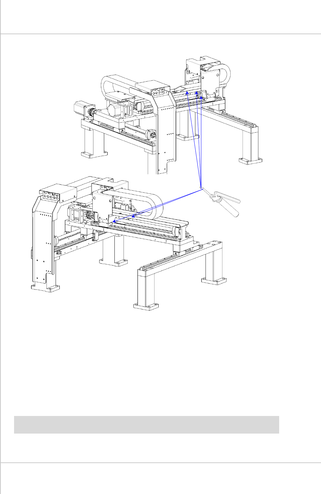
Figure 1-2. X – Axis Greasing
1. Cutthepower/theairsupplyandpressemergencyswitch.
2. OpentheFrontDoor/WindowanddisassembleRearCover/RightSideCover.
3. CleanoffremaininggreaseonLMguide&Ballscrews.
4. Putgrease(THK:HighspeedAFAgrease)inthegreasegun.
5. Applyapproximately30ccofgrease to
LM‐BLOCKandscrewnutsmovingX‐YGantry
up/down.
ÚNote:Greasethemevery6months.Regulatethegreasingintervalsdependingontheconditionof
themovingpartsintheX‐YGantryandcolorandstateofthegrease
Maintenance Manual | 25
1.2.2. COUPLING AND MOTOR CHANGE
Figure 1-3. Axis Coupling and Motor
Item Description Item Description
1 Coupling 3 Servo Motor
2 Motor Bracket
1. Cutthepower/theairsupplyandpressemergencyswitch.
2. OpentheFrontDoor/WindowanddisassembleRearCover/RightSideCover.
3. DisengageScrewShaft/CouplingfixingboltofMotorShafttomaketheCouplingmove
forward/backward.
4. DisassembleMotorfromMotorBracket.
② ① ③

26 | KY-8030 2
3DSolderPasteInspectionSystem
Version 1.0
KOH YOUNG TECHNOLOGY INC.
5. DisassembleMotorBracketandCouplingfromX‐YFrame.
6. AfterinsertingCouplingtoScrewShaftandassembleMotorBracketandMotor.
7. FixScrewShaftMotorwithShaftfixingCouplingbolt.
ÚNote
yCheckiftheCouplingmovesbetweenScrewShaftandMotorShaftwithoutobstacleandfixwith
bolt.Ifthereisanyobstacle,disengagetheMotorfixingboltandsettheAlignoftheCoupling.
yChecktheboltstateafterassembly.