20121120111955_KY8030_2_Maintenance_Manual_Eng_ver1 - 第26页
26 | KY -8030 2 3D Solder Paste Inspec tion System V ersion 1.0 K OH Y OUNG T ECHNOLOGY I NC . 5. Disassemble Motor Bracket and Coupl ing from X ‐ Y Frame. 6. After inserting Coupling to …
Maintenance Manual | 25
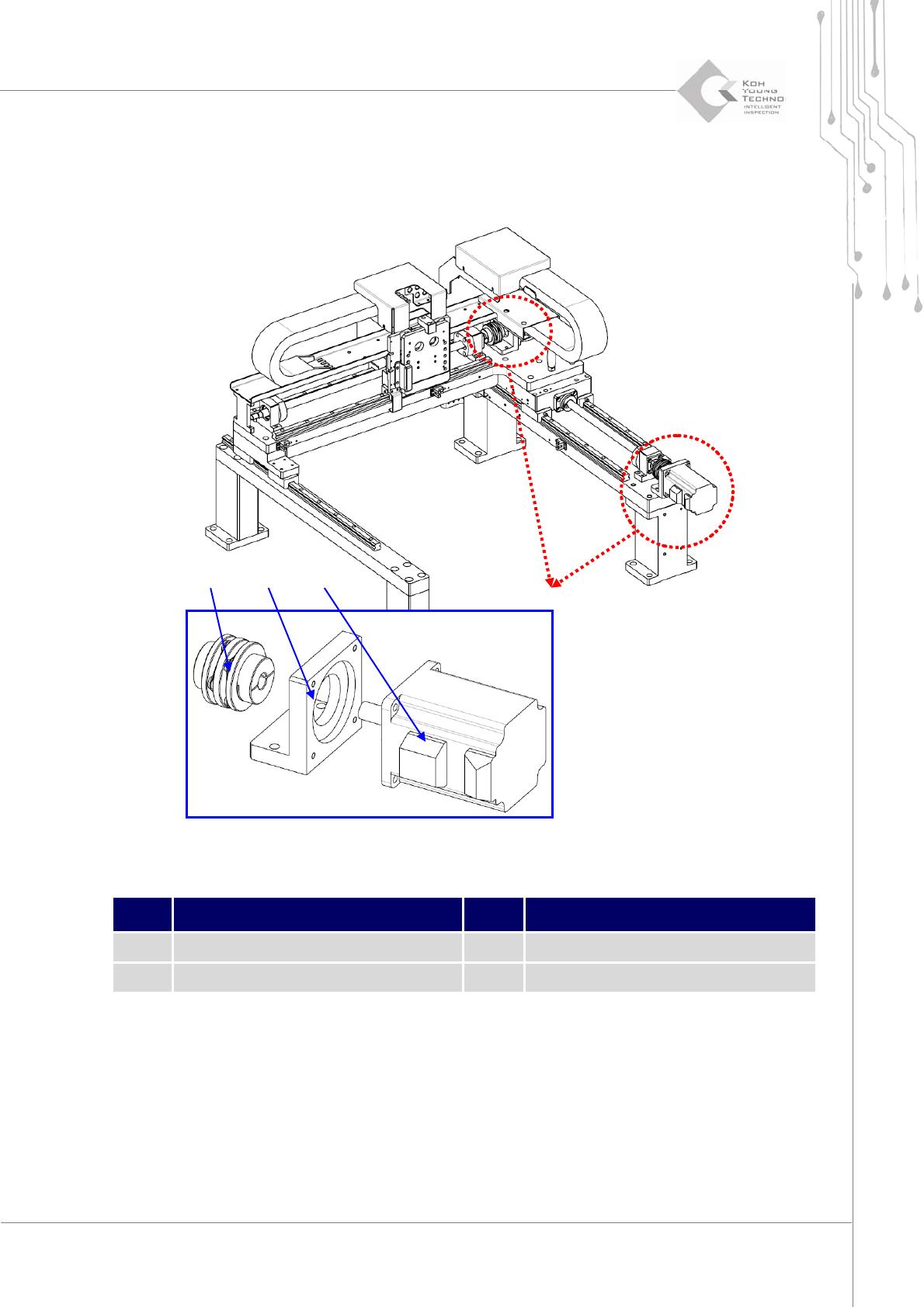
1.2.2. COUPLING AND MOTOR CHANGE
Figure 1-3. Axis Coupling and Motor
Item Description Item Description
1 Coupling 3 Servo Motor
2 Motor Bracket
1. Cutthepower/theairsupplyandpressemergencyswitch.
2. OpentheFrontDoor/WindowanddisassembleRearCover/RightSideCover.
3. DisengageScrewShaft/CouplingfixingboltofMotorShafttomaketheCouplingmove
forward/backward.
4. DisassembleMotorfromMotorBracket.
② ① ③

26 | KY-8030 2
3DSolderPasteInspectionSystem
Version 1.0
KOH YOUNG TECHNOLOGY INC.
5. DisassembleMotorBracketandCouplingfromX‐YFrame.
6. AfterinsertingCouplingtoScrewShaftandassembleMotorBracketandMotor.
7. FixScrewShaftMotorwithShaftfixingCouplingbolt.
ÚNote
yCheckiftheCouplingmovesbetweenScrewShaftandMotorShaftwithoutobstacleandfixwith
bolt.Ifthereisanyobstacle,disengagetheMotorfixingboltandsettheAlignoftheCoupling.
yChecktheboltstateafterassembly.
Maintenance Manual | 27
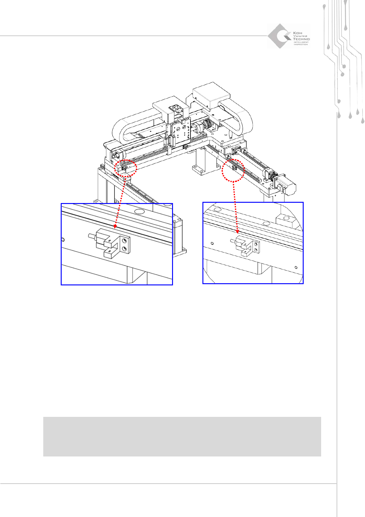
1.2.3. LIMIT SENSOR CHANGE
Figure 1-4. X-Y Limit Sensor
1. Cutthepower/theairsupplyandpressemergencyswitch.
2. OpentheFrontDoor/WindowanddisassembleRearCover/RightSideCover.
3. DisassembletheConnectorofchangingLimitSensor.
4. ChangetonewLimitSensor.
5. Combine theConnector of changed Limit Sensor and adjust the cable notto touch the
movingpartsofthesystem.
ÚNote
yManuallymovetheX‐YGantrytocheckanycontactwiththecable.
ySupplypowerandcheckiftheLimitSensorisproperlyoperatingbytheI/Oscreen.