20121120111955_KY8030_2_Maintenance_Manual_Eng_ver1 - 第29页
Maintenance Manual | 29 1.2.5. C ONVEYOR R ING B EL T AND R OLLER Figure 1-6. Timing Belt and Roller Item Description Item Description 1 Belt Guide 3 Ring Belt 2 Roller 4 T ensioner 1. Cut the power/the air s upp…
28 | KY-8030 2
3DSolderPasteInspectionSystem
Version 1.0
KOH YOUNG TECHNOLOGY INC.
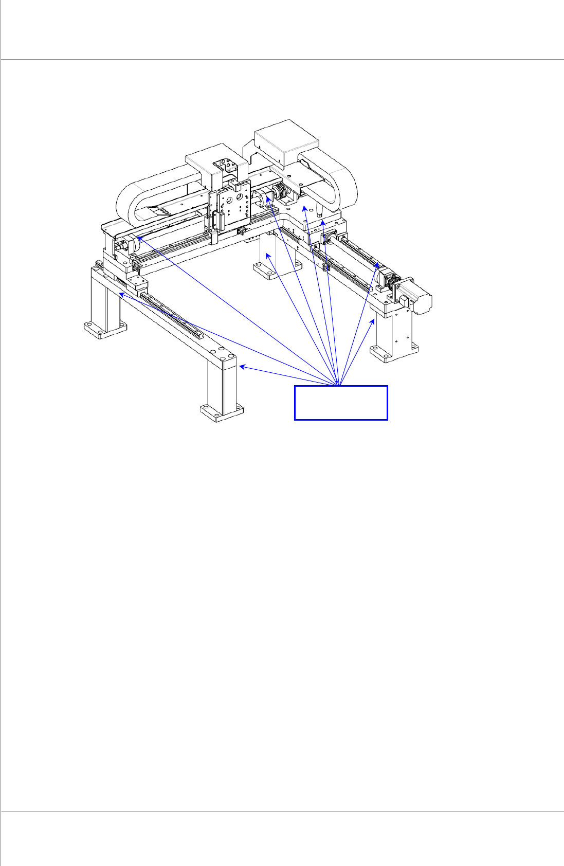
1.2.4. X-Y FRAME AND SUPPORT UNIT
Figure 1-5. X-Y Frame and Support Unit
1. Cutthepower/theairsupplyandpressemergencyswitch.
2. OpentheFrontDoor/WindowanddisassembleRearCover/RightSideCover.
3. Itisrecommendedtochecktheloosenboltsofabovewhengreasingevery6months
4. The abnormality of the positions above can result in the performance deterioration or
malfunction.
Checking
Positions
Maintenance Manual | 29
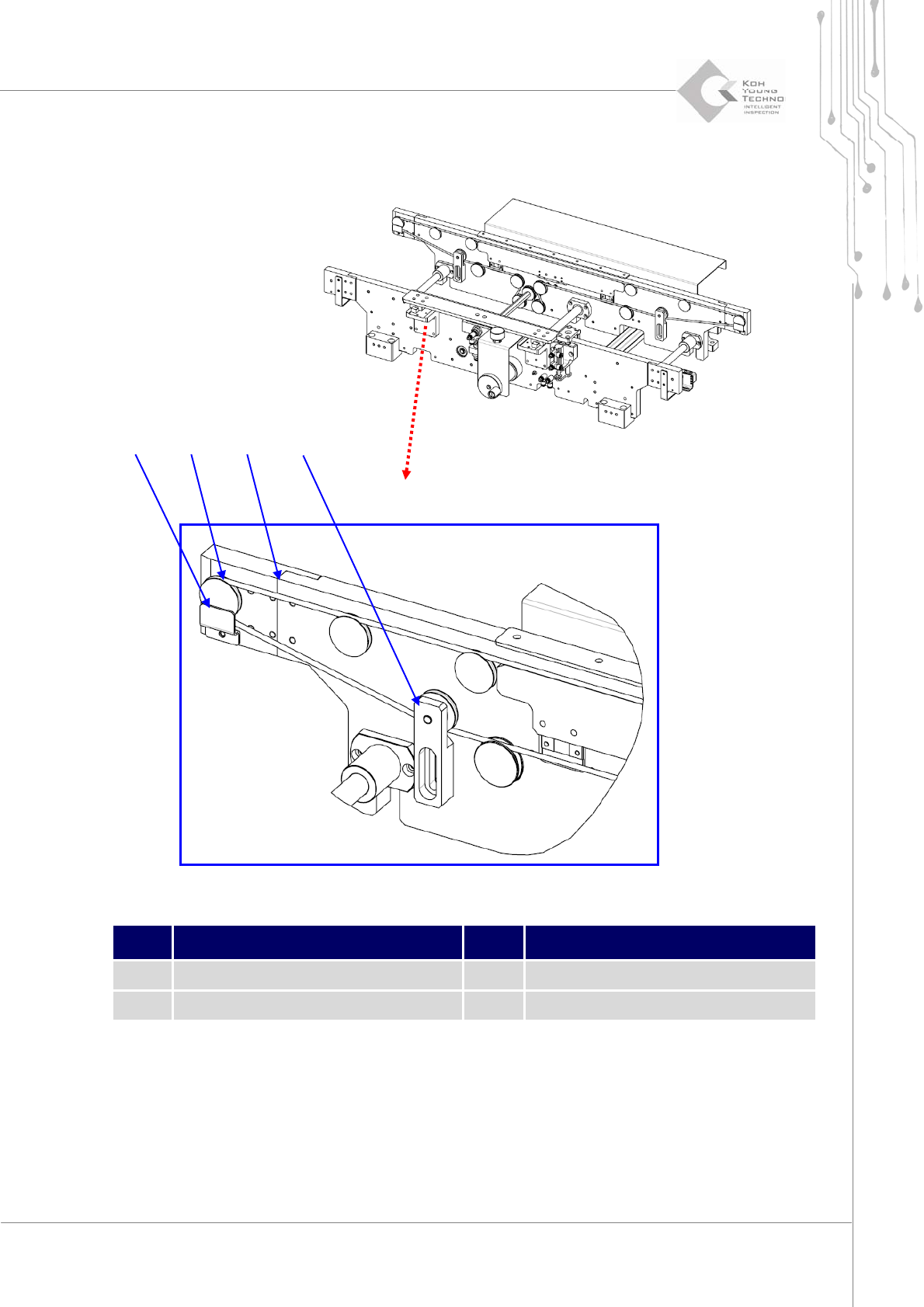
1.2.5. CONVEYOR RING BELT AND ROLLER
Figure 1-6. Timing Belt and Roller
Item Description Item Description
1 Belt Guide 3 Ring Belt
2 Roller 4 Tensioner
1. Cutthepower/theairsupplyandpressemergencyswitch.
2. OpentheFrontDoor/WindowanddisassembleRearCover/RightSideCover.
3. DisassembletheBeltGuideasthediagram.
4. Disassemble the changing Ring Belt from Roller and disassemble the Roller with
② ① ④ ③

30 | KY-8030 2
3DSolderPasteInspectionSystem
Version 1.0
KOH YOUNG TECHNOLOGY INC.
screwdriver.
5. AssembletheRollerwithscrewdriverandcombineRingBelt.
6. AssembletheBeltGuide.
7. ChecktheBeltTensionandsettotheappropriateTensionwithTensionerifitisloosen.
8. SupplypowerandchecktheRingBeltrotationstatebyturningontheRingBeltTransfer
Motor
attheI/Oscreen.
ÚNote
If Ring Belt is damaged and there isno spare Ring Belt, the damagedRing Belt can be temporarily
connectedbyheatingbothends.
AsRingBeltisanelasticbody,theTensionshouldbeadjustedbyusingTensionerinevery3month.