20121120111955_KY8030_2_Maintenance_Manual_Eng_ver1 - 第38页
38 | KY -8030 2 3D Solder Paste Inspec tion System V ersion 1.0 K OH Y OUNG T ECHNOLOGY I NC . 2. Open the Front Door/W indow and disassemble Rear Cov er/Right Side Cove r . 3. Disassemble …
Maintenance Manual | 37
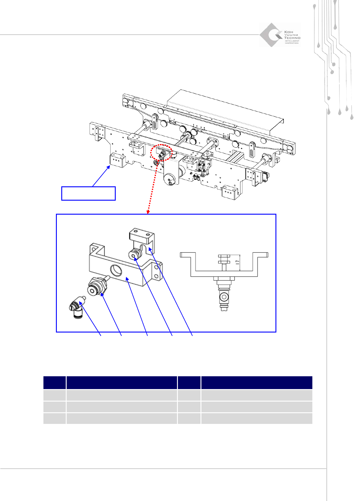
1.2.9. CONVEYOR HEIGHT GUIDE
Figure 1-10. Height Guide
Item Description Item Description
1 Spring 4 Height Guide Cylinder
2 Cylinder Shaft Joint 5 Speed Controller
3 Height Joint Bracket
1. Cutthepower/theairsupplyandpressemergencyswitch.
② ①
④
③
⑤
Fixed Rail

38 | KY-8030 2
3DSolderPasteInspectionSystem
Version 1.0
KOH YOUNG TECHNOLOGY INC.
2. Openthe FrontDoor/WindowanddisassembleRearCover/RightSideCover.
3. DisassembleHeightJointBracketfromHeightGuide.
4. Disassemble Height Cylinder Bracket from Fix Rail (first, Eliminate air‐hose from
Fitting)
5. Disassemble Height Guide Cylinder from Height Cylinder Bracket and, assemble
CylinderShaftJointandSpeedControllerat
theHeightGuideCylinder.
6. AssemblenewHeightGuideCylinderinreverseorderofdisassembly.
7. Supply power andcheck if the HeightGuide Cylinderis operating properly at theI/O
screen.
ÚNote:
HeightGuideCylinderandCylinderShaftJointshouldbeassembledasthesizeofthediagram.
IfanyforeignsubstancejammedbetweenthenarrowspaceofHeightGuideandFixRail,eliminateit
withcompressedairtopreventmalfunctioning.
Maintenance Manual | 39
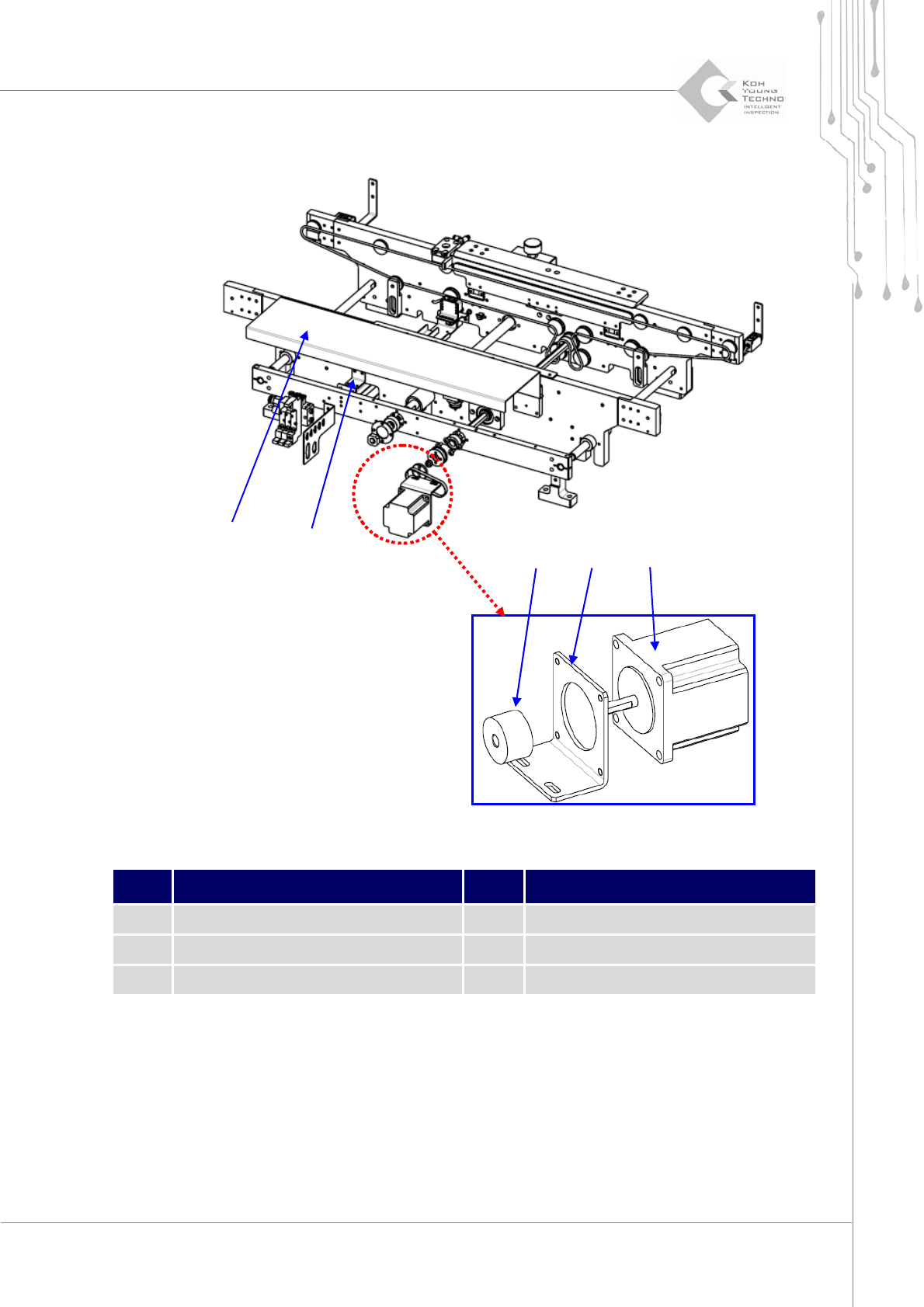
1.2.10. CONVEYOR RING BELT TRANSFER MOTOR
Figure 1-11. Ring Belt Transfer Motor
Item Description Item Description
1 Cable Motor Cover 4 Pulley Motor Bracket
2 Slide Bush Fix Bracket 5 Step Motor
3 Buffer Ring Pulley 1
1. Cutthepower/theairsupplyandpressemergencyswitch.
2. OpentheFrontDoor/WindowanddisassembleRearCover/RightSideCover.
3. DisassembleCableMotorCoverfromtheConveyor.
4. DisassemblePulleyMotorBracketfromSlideBushFixBracket.
②
①
④ ③ ⑤