20121120111955_KY8030_2_Maintenance_Manual_Eng_ver1 - 第49页
Maintenance Manual | 49 1.2.16.2. Step Motor Driver and Boards Change Figure 1-18. Step Motor Driv er & Board Item Description Item Description 1 S tep Driver 3 MCU EL 2 MCB JB Board 4 IF Board 3. Cut the power/t…
48 | KY-8030 2
3DSolderPasteInspectionSystem
Version 1.0
KOH YOUNG TECHNOLOGY INC.
② ① ③
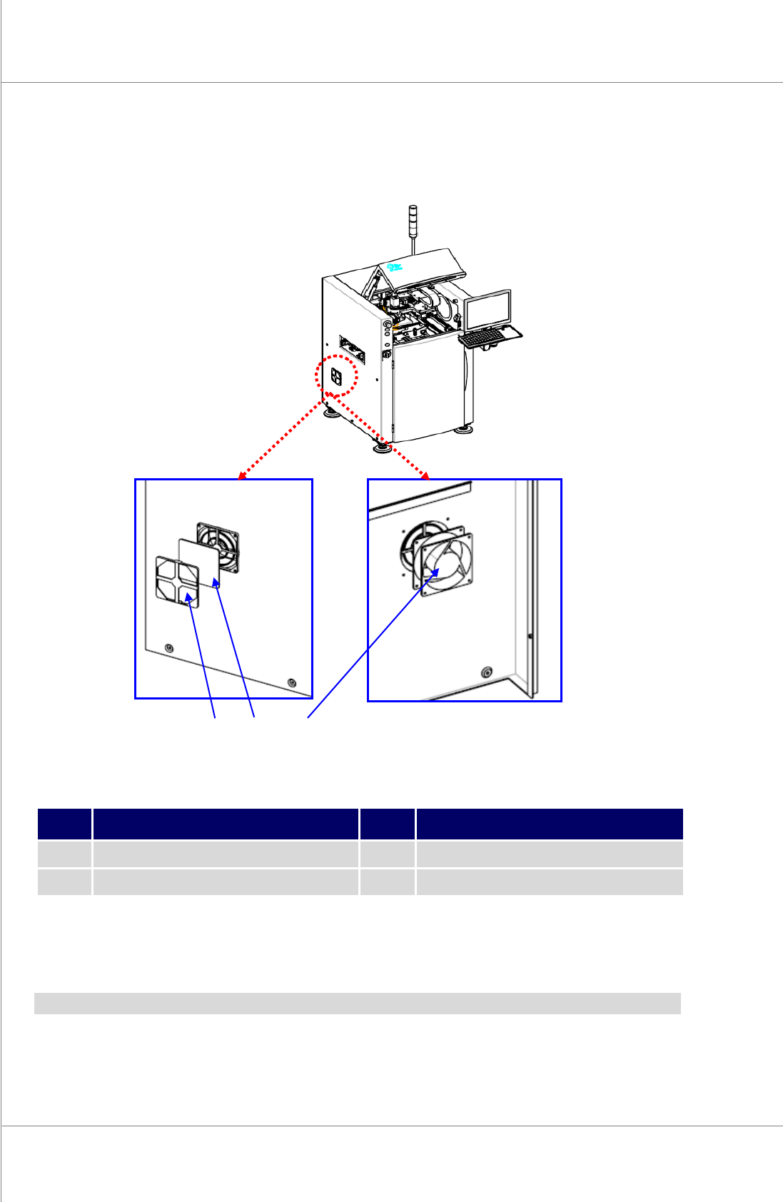
1.2.16. ELECTRIC BOX
1.2.16.1. Fan and Fan Filter Change
Figure 1-17. Fan and Fan Filter
Item Description Item Description
1 Filter cover 3 Fan
2 Filter
1. Cutthepower/theairsupplyandpressemergencyswitch.
2. DisassembleFan/FanFilterandchangetonewonesasthediagram.
Note:Filtercanbereusedaftercleaning,butchangeitafter2~3timesofreuses.
Maintenance Manual | 49
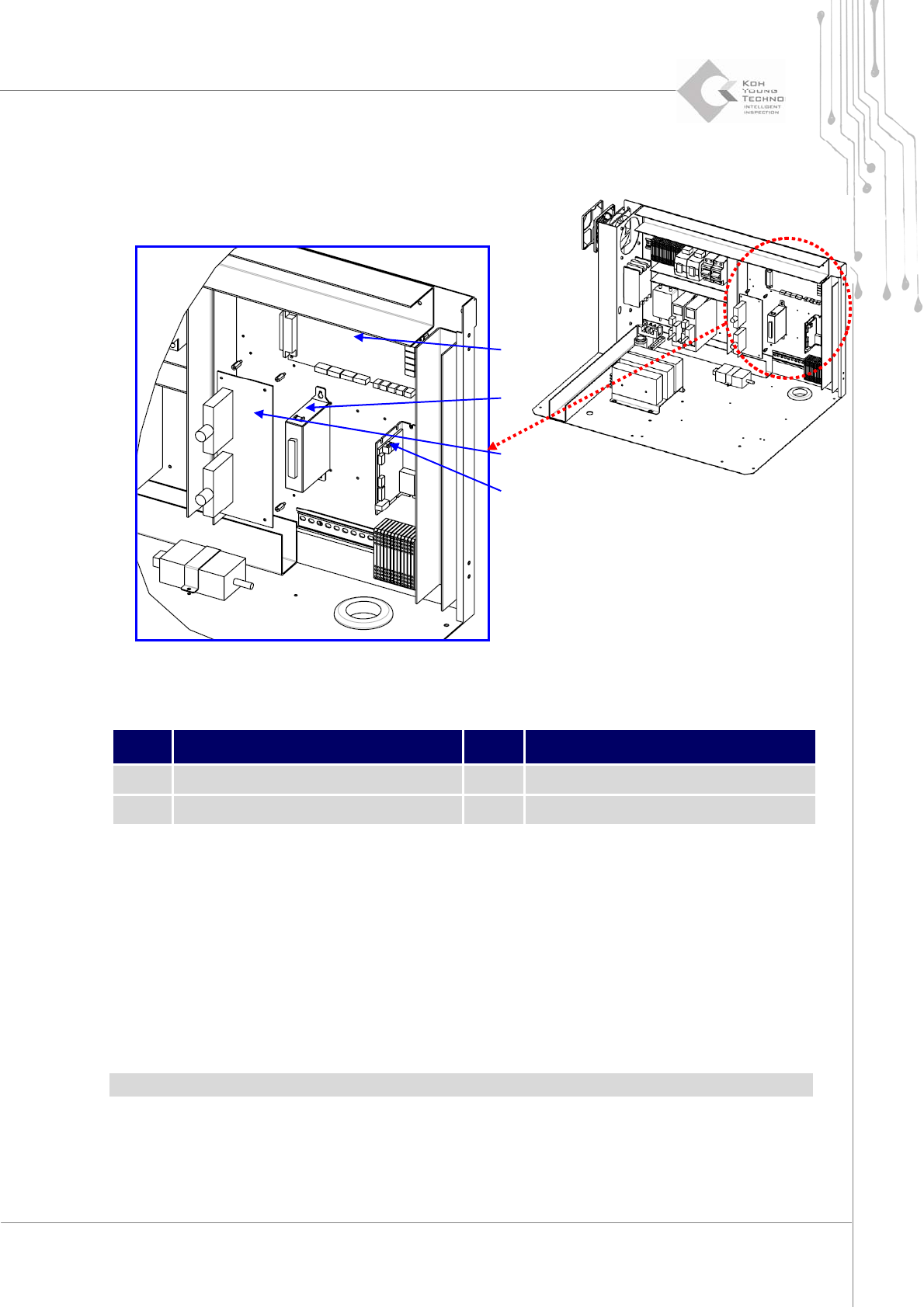
1.2.16.2. Step Motor Driver and Boards Change
Figure 1-18. Step Motor Driver & Board
Item Description Item Description
1 Step Driver 3 MCU EL
2 MCB JB Board 4 IF Board
3. Cutthepower/theairsupplyandpressemergencyswitch.
4. OpentheFrontDoor/WindowanddisassembleRearCover/RightSideCover.
5. OpentheFrontDoorofElectricBoxanddisassembletheConnectorofthechangingpart.
6. AssemblethenewpartandconnecttheConnectoraftercheckingI/ONumber.
7.
Supplypowerandcheckifthesystemisoperatingproperly.
Note:Becarefulforthehazardofelectricshockwhenchangingboard.
②
①
④
③
50 | KY-8030 2
3DSolderPasteInspectionSystem
Version 1.0
KOH YOUNG TECHNOLOGY INC.
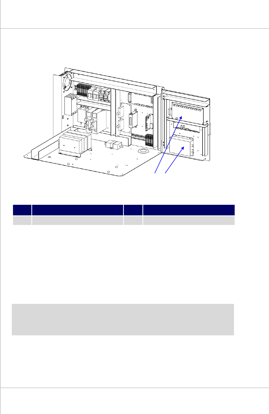
1.2.16.3. STMC Board and PZT Amplifier Change
Figure 1-19. STMC Board and PZT Amplifier
Item Description Item Description
1 PZT Amplifier 2 STMC Board
1. Cutthepower/theairsupplyandpressemergencyswitch.
2. OpentheFrontDoor/WindowanddisassembleRearCover/RightSideCover.
3. OpentheFrontDoorofElectricBoxanddisassembletheConnectorofthechangingpart.
4. AssemblethenewpartandconnecttheConnectoraftercheckingI/ONumber.
5.
Supplypowerandcheckifthesystemisoperatingproperly.
Note:
Becarefulforthehazardofelectricshockwhenchangingboard.
PZTAmplifiershouldbechangedwithProbe.
② ①