20121120111955_KY8030_2_Maintenance_Manual_Eng_ver1 - 第50页
50 | KY -8030 2 3D Solder Paste Inspec tion System V ersion 1.0 K OH Y OUNG T ECHNOLOGY I NC . 1.2.16.3. STMC Board and PZT Amplifier Change Figure 1-19. STMC Board and PZT Amplifier Item Description Item Descr…
Maintenance Manual | 49
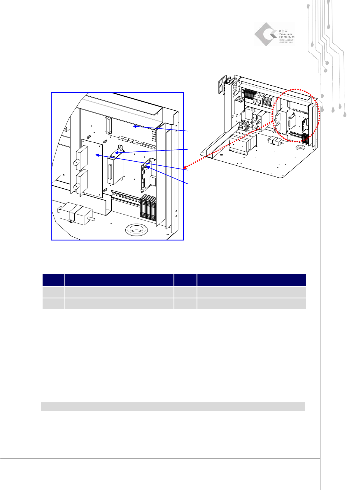
1.2.16.2. Step Motor Driver and Boards Change
Figure 1-18. Step Motor Driver & Board
Item Description Item Description
1 Step Driver 3 MCU EL
2 MCB JB Board 4 IF Board
3. Cutthepower/theairsupplyandpressemergencyswitch.
4. OpentheFrontDoor/WindowanddisassembleRearCover/RightSideCover.
5. OpentheFrontDoorofElectricBoxanddisassembletheConnectorofthechangingpart.
6. AssemblethenewpartandconnecttheConnectoraftercheckingI/ONumber.
7.
Supplypowerandcheckifthesystemisoperatingproperly.
Note:Becarefulforthehazardofelectricshockwhenchangingboard.
②
①
④
③
50 | KY-8030 2
3DSolderPasteInspectionSystem
Version 1.0
KOH YOUNG TECHNOLOGY INC.
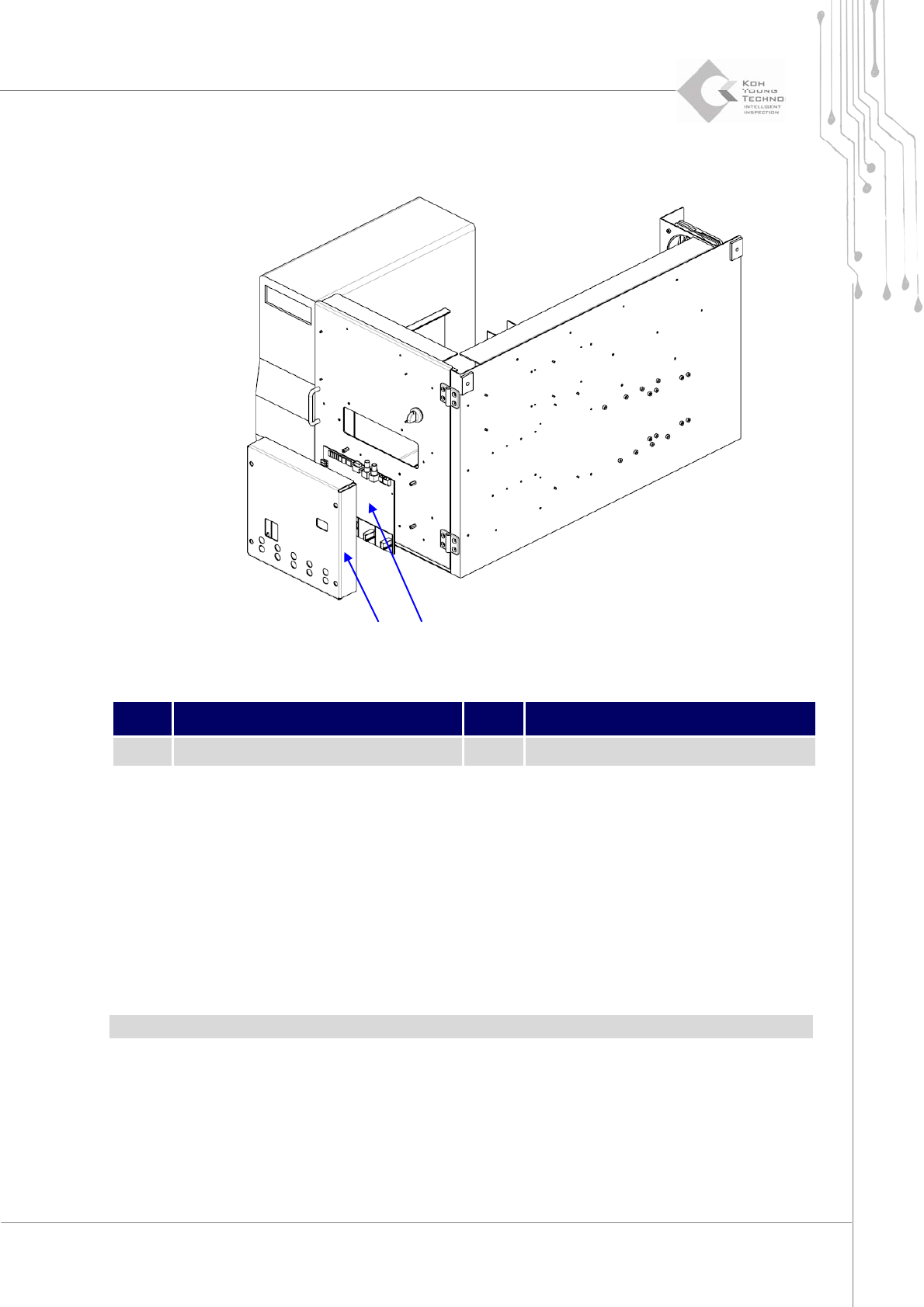
1.2.16.3. STMC Board and PZT Amplifier Change
Figure 1-19. STMC Board and PZT Amplifier
Item Description Item Description
1 PZT Amplifier 2 STMC Board
1. Cutthepower/theairsupplyandpressemergencyswitch.
2. OpentheFrontDoor/WindowanddisassembleRearCover/RightSideCover.
3. OpentheFrontDoorofElectricBoxanddisassembletheConnectorofthechangingpart.
4. AssemblethenewpartandconnecttheConnectoraftercheckingI/ONumber.
5.
Supplypowerandcheckifthesystemisoperatingproperly.
Note:
Becarefulforthehazardofelectricshockwhenchangingboard.
PZTAmplifiershouldbechangedwithProbe.
② ①
Maintenance Manual | 51
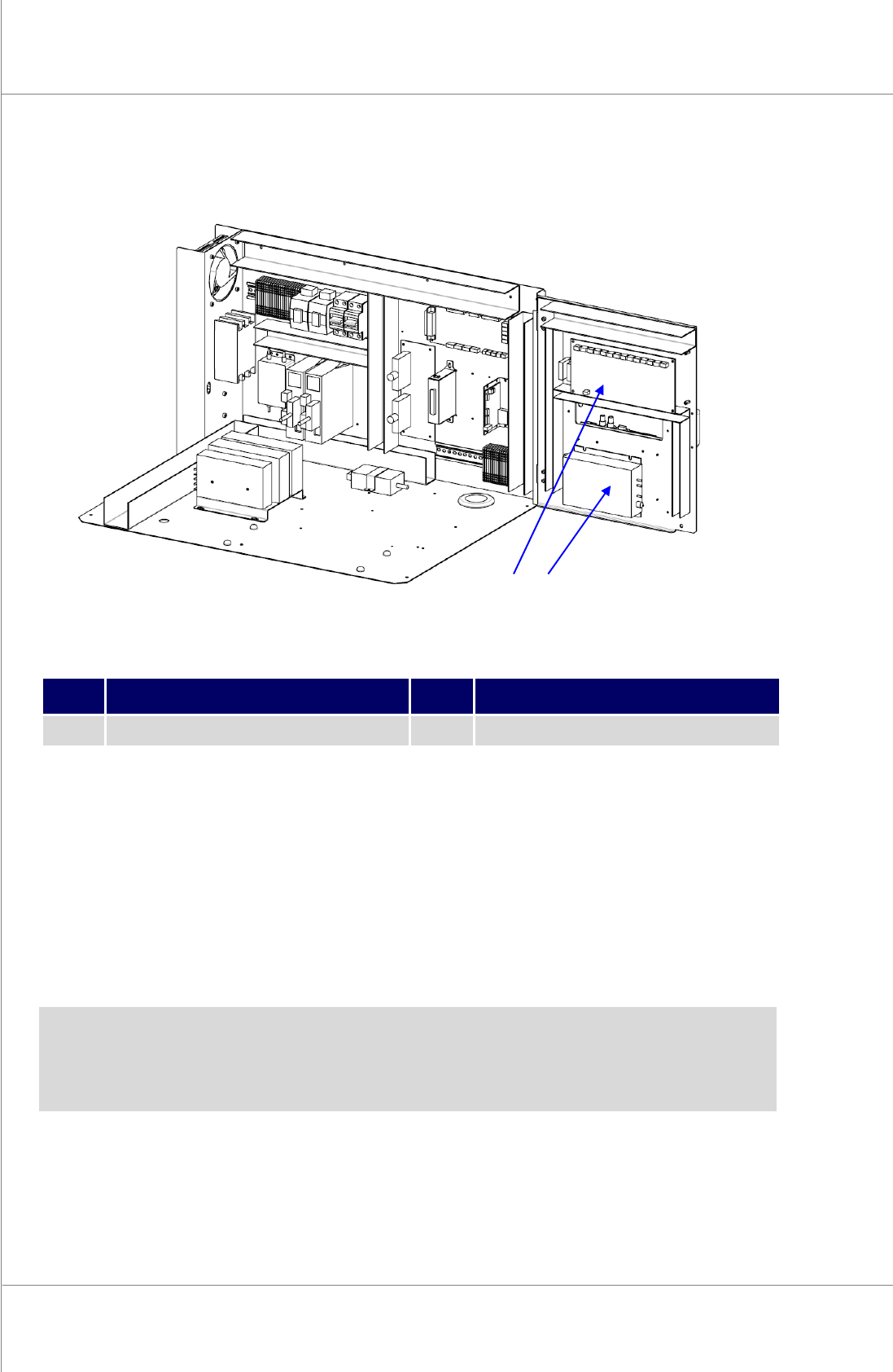
1.2.16.4. VPC Board Change
Figure 1-20. VPC Board
Item Description Item Description
1 VPC Board Cover 2 VPC Board
1. Cutthepower/theairsupplyandpressemergencyswitch.
2. OpentheFrontDoor/WindowanddisassembleRearCover/RightSideCover.
3. OpentheFrontDoorofElectricBoxanddisassembleVPCBoardConnector.
4. AssemblethenewVPCBoarandconnecttheConnectoraftercheckingI/ONumber.
5. Supplypower
andcheckifthesystemisoperatingproperly.
Note:Becarefulforthehazardofelectricshock.
②
①