20121120111955_KY8030_2_Maintenance_Manual_Eng_ver1 - 第66页
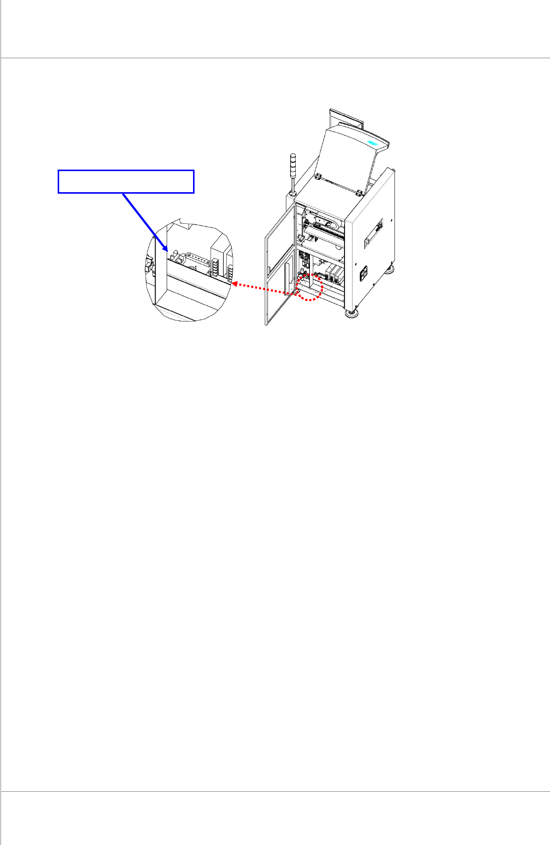
66 | KY -8030 2 3D Solder Paste Inspec tion System V ersion 1.0 K OH Y OUNG T ECHNOLOGY I NC . Figure 3-4. Power Connection Block Location Main T erminal Block

Maintenance Manual | 65
3.3. Connecting 3 Phase Power
1. Ifyourpowersupplyprovidessingle‐phasevoltage,ensurethatthevoltagebetweenthe
U&Vphases(thevoltagebetweenleadAandB)isAC220VbeforeconnectingtheKY‐
80302system.
2. Or,ifitprovides3‐phasevoltage,useonlytwooftheU(lead
A),V(leadB)andW(lead
C) phases and ensure that the voltage between the two leads is AC 220V before
connectingtheKY‐80302system.Note:ThepossibleleadcombinationsareA&B,B&C
orC&A.
3. Check the voltage between A‐
F.G. (Field Ground) and B‐F.G. leads to see if it is
approximatelyAC100V.IfitisAC100V(adiscrepancyofAC10‐30Vcanoccur),connect
the F.G. lead provided to the F.G. lead of the system. This completes power cable
connection.
4. Unlikeinstep(3),if
theACvoltagebetweenA‐F.G.andB‐F.G.leadsis0(zero),itmaybe
thattheF.G.leadprovidedisfaulty.Shouldthisoccur,donotconnecttheF.G.leadtothe
systemandfollowthestepsfrom(5)instead.
5. Ifaproblemoccursasdescribedin
step(4),checktheACvoltagesbetweenleadAthat
willbewiredtothesystemandoneofthefeetofonemachine,andbetweenleadBthat
willbewiredtothesystemandoneofthefeetoftheothermachinetoseeiftheF.G.lead
provided
complies with the conditionstated instep(4),and thenfollowthestepsfrom
(6)
6. IfthefootoftheothermachineoffersanF.G.lead,connectittothesystem
7. Ifnot,donotconnectittothesystembutconsulttheadministrator.
8. In the case
of step (7), if static electricity or sparks tend to occur when a PCB in the
system or another machine istouched, thefootof the machine can be connected to the
systemalthoughitdoesnotofferanF.G.leadasdescribedinstep(3). Inthiscase,make
sure
to consult the administratorasthe systemcan be affected by powerfluctuationor
noise.
66 | KY-8030 2
3DSolderPasteInspectionSystem
Version 1.0
KOH YOUNG TECHNOLOGY INC.
Figure 3-4. Power Connection Block Location
Main Terminal Block
Maintenance Manual | 67
3.4. Package and Storage
3.4.1. PACKAGING ITEMS
3DSolderInspectionSystem(KY‐80302)
LCDMonitor
Computer
TowerLamp
StandardPartBox(UserManual,CDincluded)
3.4.2. PACKAGING
1. Fixthebottomofthefoot,locatedonthelowerpartofthemachine,withwoodenPlator
StopperBracket.
2. FixtheBufferConveyor,locatedontheoutsideofthemachine,withspecialfixingJigor
Bracket.
3. Pack the Monitor, Computer and Tower Lamp, located on the outside
of the machine,
separatelyafterdetachingthemfromthemachine.
4. Fix the Monitor support, keyboard, keyboard support, mouse and mouse pad to the
machinesothattheycannotmove.
5. Fix the probe, Conveyor, internal operating part X, Y and Z axis with fixing Jig or
Bracket.
6. Put
soft cloth or polyester sheet on the acrylic door to prevent damages, wrap the
machinewithadhesivevinylwrapandfoams.
7. Make the whole wooden box (crate) with the machine inside, and then attach the
Shippingmark.
8. Attach the sticker with information including sender, receiver, Case No. and Gross
Weightwrittenon.
※ Caution:Avoidimpactorpressureontheacrylicdoororsystempackage.
Forkliftthesystemfromtheside.Ifliftedfromthefrontorback,thesystemcanlosebalanceandfall.
Observethepackagingruletopreventdamageorscratch.
Useair‐ridetrucktopreventdamagefortheshortdistancetransportation.
Whenexporting,vacuumpackagethesystembythepackagingexpert.