KE-3010_SPE_EN - 第26页
- 21 - * For the L - W ide P W B specification, any pin reference option cannot be selected. P W B transport dire ction Placement di sable r ange 61mm 20mm 22.6mm 0 to 292 mm M ov in g pa rt 4.5mm Placement di sable r an…
- 20 -
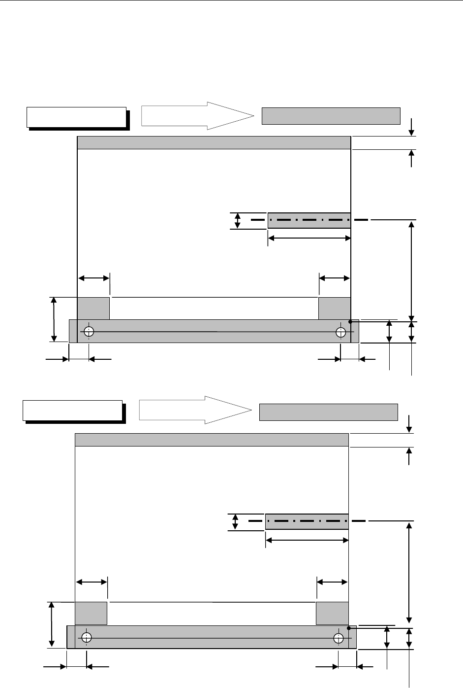
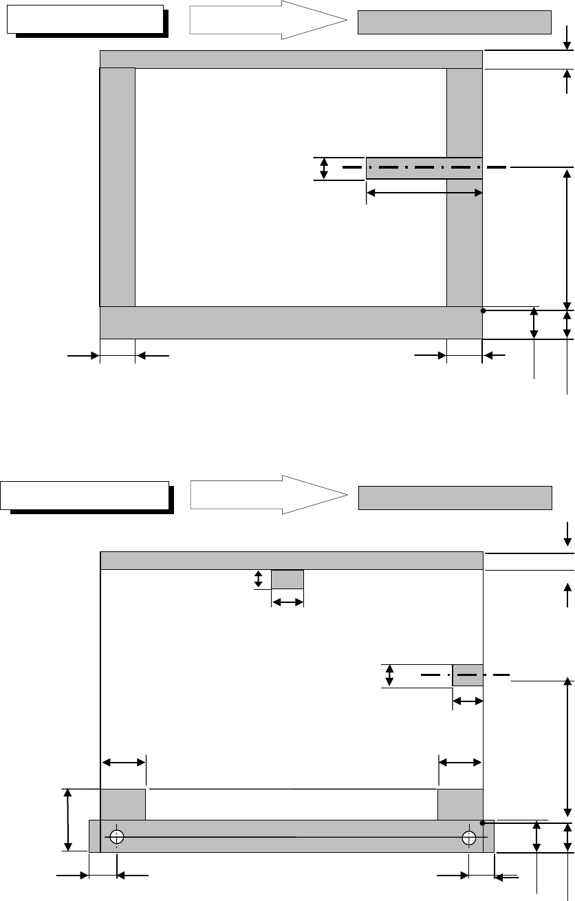
4.7.4. Support pin installation disable range
These dimensions are factory-set ones. The restriction range is added when the reference
pin is used. The PWN transport direction is for a clockwise flow as shown in the figure. In
the case of a flow in the opposite direction, the support pin disable range is bisymmetrical to
the figure.
・PWN bottom drawing
26mm
39.3mm
26.5mm
61mm
26mm
26.5mm
20mm
23mm
22.6mm
0 to 292 mm Moving part
4.5mm
Placement disable range
PWB transport direction
Placement disable range
26mm
39.3mm
26.5mm
61mm
26mm
26.5mm
20mm
23mm
22.6mm
0 to 187 mm Moving part
4.5mm
Placement disable range
PWB transport direction
Placement disable range
M PWB specification
L PWB specification
- 21 -
* For the L-Wide PWB specification, any pin reference option cannot be selected.
PWB transport direction
Placement disable range
61mm
20mm
22.6mm
0 to 292 mm Moving part
4.5mm
Placement disable range
PWB transport direction
Placement disable range
24.5mm
24.5mm
23mm
L-Wide PWB specification
XL Wide PWB specification
26mm
39.3mm
26.5mm
13mm
26mm
26.5mm
20mm
23mm
22.6mm
0 to 280.6 mm Moving part
6.5mm
Placement disable range
18.5mm
28mm
- 22 -
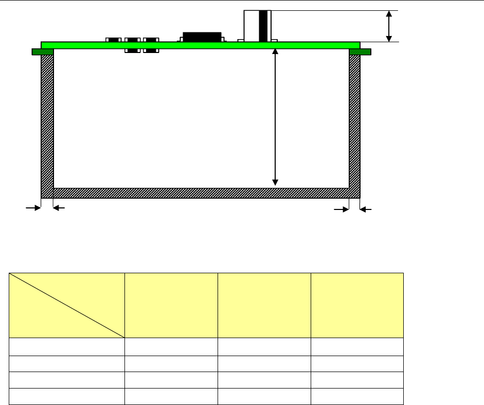
4.7.5. Placement enable range on the top and bottom surfaces of PWB
*1:Maximum heights of components that can be placed
Maximum
Component size
Specification
of component height
Component
diagonal less than
50 mm
Component
diagonal 50 mm or
more to less
than 88 mm
Component
diagonal 88 mm or
more
SC specification 6mm
- -
NC specification 12mm 12mm 5mm
HC specification 20mm 20mm 5mm
EC specification 25mm 20mm 5mm
PWBs clamping method
This is a method to use the PWB top surface as a reference to have both the PWB front and
rear ends each at the fixed and movable sides supported to the transport rails, then, to clamp
the PWBs.
PWB width adjusting methods
* Standard: Manually adjusting method with your hand
* Option: Automatic PWB width adjusting method via a motor
(Minimum board size: 50.0 mm x 50.0 mm)
PWB positioning reference
* Shape reference
* Pine reference (optional)
Maximum *1
SC: 6mm
NC: 12mm
HC: 20mm
EC: 25mm
3mm
3mm
MAX. 40 mm