KE-3010_SPE_EN - 第12页
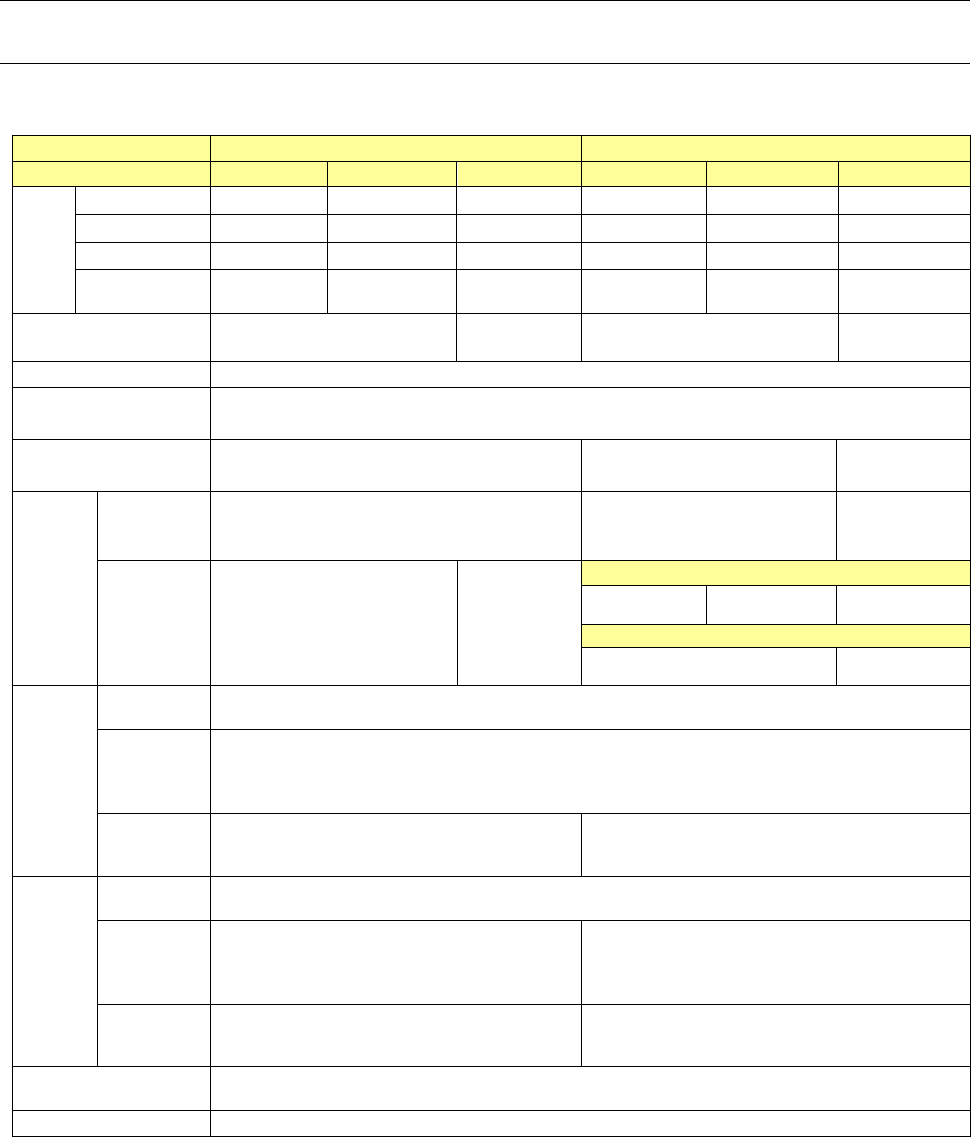
- 7 - Model name KE - 3010 KE - 3020V KE - 3020VR Feeder ban k (Electric ty pe /Combination ty pe: for both a mechanical f eeder and an electri c feeder) Electric feeder bank ( fixed ty pe) ● *1 ● *1 ● *1 Electric fee de…

- 6 -
Machine style
KE-3010 KE-3020V KE-3020VR
HOD
●*1
●*1
●*1
DVD/CD-ROM drive (USB)
●
●
●
FD drive (USB)
●
●
●
Equipment device
Feeder float sensor
○
○
○
Automatic tool change unit (ATC)
○
○
○
Large-shape component scrap box
-
○
○
Flexible calibration system
(
FCS
)
○
○
○
FCS adjustment jig
●
●
●
Feeder position indicator (FPI)
●*1
●*1
●*1
SOT direction inspection table
●*1
●*1
●*1
Component verification (CVS)
●*1
●*1
●*1
Coplanarity
●*1 *6
●*1
●*1
Ionizer
●*1
●*1
●*1
Fluxer: Type 2 (To be attached on the main unit)
●*1*13*14
●*1*13*14
●*1*13*14
Simplified load control
●*1
●*1
●*1
Solder print recognition placement position correction
●*1
●*1
●*1
Bottom view type multi-code reader
●*1
●*1
●*1
Production support system
Component database
○*7
○*7
○*7
External programing unit (EPU)
●
●
●
Floor productivity operating system
Production support system
・
IS
●
●
●
・
IS Lite
●
●
●
・
JaNets
●
●
●
Production management system
・
IFS-NX
●
●
●
White list type anti-virus software
●*1
●*1
●*1
Feeder bank (Mechanical type)
Mechanical feeder bank (fixed type)
○
○
○
Mechanical feeder bank (trolley type)
●*1
●*1
●*1
Trolley for mechanical feeder
●*1
●*1
●*1
Intelli trolley(RFID) for mechanical feeder
●*8
●*8
●*8
Connector bracket
●*1
●*1
●*1
IC collection belt unit
●
●
●
Component supply unit
- Tape feeder/bulk feeder
- Stick feeder / Stacked stick feeder
●
*8
●*8
●
*8
●*8
●
*8
●*8
Tray supply unit
- MTC
*14
- MTS
- DTS
- Tray holder
●*8 *9 ●*8 *9 ●*8 *9
Fluxer: Type 3 (To be attached on a bank/rear side only)
●*1*13
●*1*13
●*1*13
Rotary-type solder transfer device
(To be attached on a bank/front side only)
●*1*13 ●*1*13 ●*1*13
Tape reel mounting base
●
●
●
Tape cutter
●
●
●
Trash box
●
●
●
Wafer supply unit
Multi-die server (DF01)
●*15
●*15
●*15

- 7 -
Model name
KE-3010 KE-3020V KE-3020VR
Feeder bank (Electric type/Combination type: for both a mechanical feeder and an electric feeder)
Electric feeder bank (fixed type)
●*1
●*1
●*1
Electric feeder bank (trolley type)
●*1
●*1
●*1
Feeder exchange trolley for electric feeder(EF)
●*1
●*1
●*1
Feeder exchange trolley for electric feeder(RF)
●*1*18
●*1*18
●*1*18
Intelli trolley(RFID) for electric feeder
●*8
●*8
●*8
Tape cutter unit
●*1
●*1
●*1
IC collection belt unit
● ● ●
Component supply unit
- EF series electric feeder
●*8 *16
●*8 *16
●*8 *16
- RF series electric feeder
●*18
●*18
●*18
- Stick feeder
●*8 *16
●*8 *16
●*8 *16
Tray supply unit
- MTC
*14
●
*8 *9
●
*8 *9
●
*8 *9
- MTS
●*8 *9
●*8 *9
●*8 *9
- DTS
●
*8 *9 *17
●
*8 *9 *17
●
*8 *9 *17
- Tray holder
●*8 *9
●*8 *9
●*8 *9
Wafer supply unit
Multi-die server (DF01)
●*15
●*15
●*15
Fluxer: Type 3 (To be attached on a bank/rear side only)
●*1*13*17
●*1*13*17
●*1*13*17
Rotary-type solder transfer device
(To be attached on a bank/front side only)
●*1*13*17 ●*1*13*17 ●*1*13*17
Feeder setup stand for E-feeder (EF)
●
●
●
Feeder setup stand for E-feeder (RF)
●
●
●
RF_ETF_Attachment
●*16
●*16
●*16
Offline power supply for electric bank
●
●
●
Feeder bank for both mechanical type and electric type
●*1 *10
●*1 *10
●*1 *10
*1 This option is a factory-set option.
*2 Both MNVC and component recognition camera are provided as a set.
*3 This is applicable to the M PWB machine and L PWB machine.
*4 When the L-wide PWB specification is adopted, pin reference cannot be selected.
*5 Applicable only to the L PWB machine.
*6 The MNVC function is required.
*7 To use the component database, a PC is separately required.
*8 To use the production management system, Applicable to FRID is required.
(For mountable models and models for which a countermeasure can be taken later, refer to the
PRODUCT SPECIFICATIONS of production management system.)
*9 For installing, MTS, it is necessary to change the rear side of the main unit so that a feeder exchange
trolley can be mounted on it.
*10 For the options of both mechanical and electric feeder banks, refer to the description of each feeder
bank.
*11 This is not mounted on the machine when a placement monitor is selected.
*12 LNC 61 and LNC62 are heads exclusively designed for a placement monitor into which an
ultra-miniature camera is incorporated.
The specifications of recognition with laser are equivalent with those of an LNC60.
*13 Select either of a fluxer and a rotary-type solder transfer device.
*14 You cannot select both a fluxer (Type 2: to be attached on the main unit) and an MTC at the same
time.
*15 This unit can be attached on the rear bank of the main unit designed for a feeder exchange trolley.
*16 Attach the RF_ETF_Attachment when feeders for electric bank are used by a feeder trolley (RF). (If you
use the RF_ETF_Attachment, non-teaching and synchronous adsorption guarantee are excluded.)
*17 It does not correspond to the Feeder exchange trolley RF.
*18 It's necessary to change the cutter unit to the latest to use "Feeder exchange trolley RF".
- 8 -
4.
Specifications
4.1. Features of each model
① Basic specifications
KE-3010
KE-3020V / KE-3020VR
Board specifications
M PWB
L PWB
XL PWB
M PWB
L PWB
XL PWB
Board
dimensi
ons
Standard
330×250 ㎜ 410×360 ㎜ 610×560 ㎜ 330×250 ㎜ 410×360 ㎜ 610×560 ㎜
L-Wide -
510×360 ㎜
- -
510×360 ㎜
-
Long PWB
650x250 ㎜ 800×360 ㎜ 1210×560 ㎜ 650x250 ㎜ 800×360 ㎜ 1210×560 ㎜
L-Wide(long
PWB)
-
1010×360 ㎜
- -
1010×360 ㎜
-
Board transport reference
position
Front reference
Rear reference
Front reference
Front reference
Rear reference
Front reference
Supported languages
English, Japanese and Chinese is selected in real time.
Conveyor height
900 ㎜±20 ㎜
950 ㎜±20 ㎜ (option, EN machine: standard)
Component height
SC(6 ㎜)
NC(12 ㎜)
NC(12 ㎜)
HC(20 ㎜)
EC(25 ㎜)
Componen
t
placement
speed
* See
Note
1, 2, and 4
.
Chip
component
(IPC9850)
18,500(CPH) 17,100(CPH) 15,300(CPH)
IC component
9,000(CPH)
* S
ee Note 3.
7,000 (CPH)
* S
ee Note 3.
KE-3020V(LNC60+IC head)
9,470(CPH) 9,350(CPH) 7,100(CPH)
KE-3020VR(LNC60)
9,000(CPH) 7,000(CPH)
Componen
t size
*
See Note
1.
Laser
recognition
0402~□33.5 ㎜ or opposite angle 47 ㎜
Image
recognition
(MNVC)
* See Note 3
Standard camera: □3~□33.5 ㎜
High-resolution camera (option): 1005~□20 ㎜
Image
recognition
(IC head)
-
Standard camera: □3~50×150 ㎜ or □74 ㎜
High-resolution camera: 1005~50×120 ㎜ or □48 ㎜
Placement
accuracy
*
See Note
1.
Laser
recognition
±50μm (Cpk≧1)
Image
recognition
(MNVC)
* See Note 3
±40μm ±40μm
Image
recognition
(IC head)
- ±30μm
Number of component to
be placed
A maximum of 160 types (when using EF08HD)
EN Specifications
Enable
* Note 1: For details of specifications, refer to Section 4-3 Placement cycle time, Section 4-5 Target
components, and Section 4-6 Placement accuracy.
For each specification of MNVC (option) of KE-3010, refer to Section 4-3, Section 4-5, and Section
4-6. which are aforementioned.
* Note 2: Transport: Front reference, Component height: 6 mm (KE-3010)/12 mm (KE-3020V/20VR M
specification/L specification)/25 mm (KE-3020V/20VR XL specification)
* Note 3: It is the approximate value when MNVC (option for KE-3010) is used and/or the components are
simultaneously picked up with 6 nozzles.
*Note 4: Except case of using the RF_ETF_Attachment.