KE-3010_SPE_EN - 第13页
- 8 - 4. S pecifi catio ns 4.1. Features of each model ① Basic specifications KE - 3010 KE - 3020V / KE - 3020VR Board specific ations M PW B L PW B XL P W B M PW B L PW B XL P W B Board dimensi ons S tandard 330×250 ㎜ 4…

- 7 -
Model name
KE-3010 KE-3020V KE-3020VR
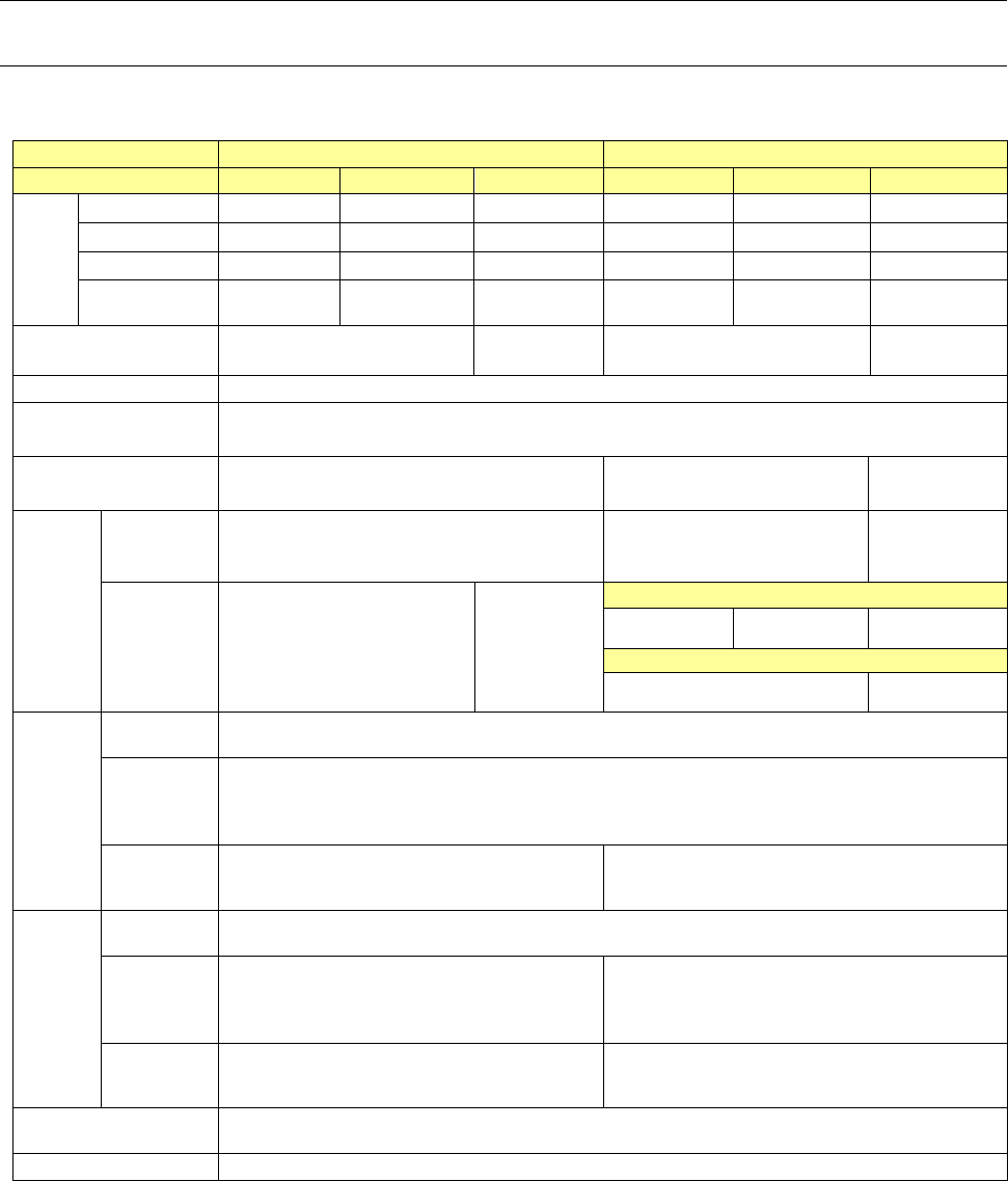
Feeder bank (Electric type/Combination type: for both a mechanical feeder and an electric feeder)
Electric feeder bank (fixed type)
●*1
●*1
●*1
Electric feeder bank (trolley type)
●*1
●*1
●*1
Feeder exchange trolley for electric feeder(EF)
●*1
●*1
●*1
Feeder exchange trolley for electric feeder(RF)
●*1*18
●*1*18
●*1*18
Intelli trolley(RFID) for electric feeder
●*8
●*8
●*8
Tape cutter unit
●*1
●*1
●*1
IC collection belt unit
● ● ●
Component supply unit
- EF series electric feeder
●*8 *16
●*8 *16
●*8 *16
- RF series electric feeder
●*18
●*18
●*18
- Stick feeder
●*8 *16
●*8 *16
●*8 *16
Tray supply unit
- MTC
*14
●
*8 *9
●
*8 *9
●
*8 *9
- MTS
●*8 *9
●*8 *9
●*8 *9
- DTS
●
*8 *9 *17
●
*8 *9 *17
●
*8 *9 *17
- Tray holder
●*8 *9
●*8 *9
●*8 *9
Wafer supply unit
Multi-die server (DF01)
●*15
●*15
●*15
Fluxer: Type 3 (To be attached on a bank/rear side only)
●*1*13*17
●*1*13*17
●*1*13*17
Rotary-type solder transfer device
(To be attached on a bank/front side only)
●*1*13*17 ●*1*13*17 ●*1*13*17
Feeder setup stand for E-feeder (EF)
●
●
●
Feeder setup stand for E-feeder (RF)
●
●
●
RF_ETF_Attachment
●*16
●*16
●*16
Offline power supply for electric bank
●
●
●
Feeder bank for both mechanical type and electric type
●*1 *10
●*1 *10
●*1 *10
*1 This option is a factory-set option.
*2 Both MNVC and component recognition camera are provided as a set.
*3 This is applicable to the M PWB machine and L PWB machine.
*4 When the L-wide PWB specification is adopted, pin reference cannot be selected.
*5 Applicable only to the L PWB machine.
*6 The MNVC function is required.
*7 To use the component database, a PC is separately required.
*8 To use the production management system, Applicable to FRID is required.
(For mountable models and models for which a countermeasure can be taken later, refer to the
PRODUCT SPECIFICATIONS of production management system.)
*9 For installing, MTS, it is necessary to change the rear side of the main unit so that a feeder exchange
trolley can be mounted on it.
*10 For the options of both mechanical and electric feeder banks, refer to the description of each feeder
bank.
*11 This is not mounted on the machine when a placement monitor is selected.
*12 LNC 61 and LNC62 are heads exclusively designed for a placement monitor into which an
ultra-miniature camera is incorporated.
The specifications of recognition with laser are equivalent with those of an LNC60.
*13 Select either of a fluxer and a rotary-type solder transfer device.
*14 You cannot select both a fluxer (Type 2: to be attached on the main unit) and an MTC at the same
time.
*15 This unit can be attached on the rear bank of the main unit designed for a feeder exchange trolley.
*16 Attach the RF_ETF_Attachment when feeders for electric bank are used by a feeder trolley (RF). (If you
use the RF_ETF_Attachment, non-teaching and synchronous adsorption guarantee are excluded.)
*17 It does not correspond to the Feeder exchange trolley RF.
*18 It's necessary to change the cutter unit to the latest to use "Feeder exchange trolley RF".
- 8 -
4.
Specifications
4.1. Features of each model
① Basic specifications
KE-3010
KE-3020V / KE-3020VR
Board specifications
M PWB
L PWB
XL PWB
M PWB
L PWB
XL PWB
Board
dimensi
ons
Standard
330×250 ㎜ 410×360 ㎜ 610×560 ㎜ 330×250 ㎜ 410×360 ㎜ 610×560 ㎜
L-Wide -
510×360 ㎜
- -
510×360 ㎜
-
Long PWB
650x250 ㎜ 800×360 ㎜ 1210×560 ㎜ 650x250 ㎜ 800×360 ㎜ 1210×560 ㎜
L-Wide(long
PWB)
-
1010×360 ㎜
- -
1010×360 ㎜
-
Board transport reference
position
Front reference
Rear reference
Front reference
Front reference
Rear reference
Front reference
Supported languages
English, Japanese and Chinese is selected in real time.
Conveyor height
900 ㎜±20 ㎜
950 ㎜±20 ㎜ (option, EN machine: standard)
Component height
SC(6 ㎜)
NC(12 ㎜)
NC(12 ㎜)
HC(20 ㎜)
EC(25 ㎜)
Componen
t
placement
speed
* See
Note
1, 2, and 4
.
Chip
component
(IPC9850)
18,500(CPH) 17,100(CPH) 15,300(CPH)
IC component
9,000(CPH)
* S
ee Note 3.
7,000 (CPH)
* S
ee Note 3.
KE-3020V(LNC60+IC head)
9,470(CPH) 9,350(CPH) 7,100(CPH)
KE-3020VR(LNC60)
9,000(CPH) 7,000(CPH)
Componen
t size
*
See Note
1.
Laser
recognition
0402~□33.5 ㎜ or opposite angle 47 ㎜
Image
recognition
(MNVC)
* See Note 3
Standard camera: □3~□33.5 ㎜
High-resolution camera (option): 1005~□20 ㎜
Image
recognition
(IC head)
-
Standard camera: □3~50×150 ㎜ or □74 ㎜
High-resolution camera: 1005~50×120 ㎜ or □48 ㎜
Placement
accuracy
*
See Note
1.
Laser
recognition
±50μm (Cpk≧1)
Image
recognition
(MNVC)
* See Note 3
±40μm ±40μm
Image
recognition
(IC head)
- ±30μm
Number of component to
be placed
A maximum of 160 types (when using EF08HD)
EN Specifications
Enable
* Note 1: For details of specifications, refer to Section 4-3 Placement cycle time, Section 4-5 Target
components, and Section 4-6 Placement accuracy.
For each specification of MNVC (option) of KE-3010, refer to Section 4-3, Section 4-5, and Section
4-6. which are aforementioned.
* Note 2: Transport: Front reference, Component height: 6 mm (KE-3010)/12 mm (KE-3020V/20VR M
specification/L specification)/25 mm (KE-3020V/20VR XL specification)
* Note 3: It is the approximate value when MNVC (option for KE-3010) is used and/or the components are
simultaneously picked up with 6 nozzles.
*Note 4: Except case of using the RF_ETF_Attachment.

- 9 -
② The relationship among the model names, recognition devices and heads is shown below.
KE-3010
KE-3020V
KE-3020VR
Explanation
LNC60 ○ ○ ○
This can place small-shape and thin chips at a
high speed by 6 nozzles.
IC
head
(CDS)
- ○ -
This head can place IC components of
large-shape QFP, CSP, BGA, etc. by vision
recognition.
IC
head
(FMLA)
- - ○
This head can place components by laser
recognition and vision recognition. All types of
nozzles such as gripper nozzle and particular
ordering nozzle can be used for the IC head
(FMLA).
VCS
-
* See
Note 1.
○ ○
VCS can perform vision recognition of IC
components. An optional high-resolution camera
can be added.
*Note 1: The standard camera is attached to MNVC (option). The high-resolution camera is
also attached.
③ Recognition function
KE-3010 KE-3020V KE-3020VR Explanation
MNVC Option
○ ○
Vision recognition can be performed by LNC60.
IC components of small-shape QFP, CSP, BGA,
etc. can be placed at a high speed. Vision
recognition can be performed by VCS in the
high-speed non-stop mode. (S-VCS)