KE-3010_SPE_EN - 第14页
- 9 - ② The relationship among the model names, recognition dev ices and heads is show n below . KE - 301 0 KE - 3020V KE - 3020VR Explanat ion LNC60 ○ ○ ○ This c an place sm all - shap e and thin chi ps at a high spee d…
- 8 -
4.
Specifications
4.1. Features of each model
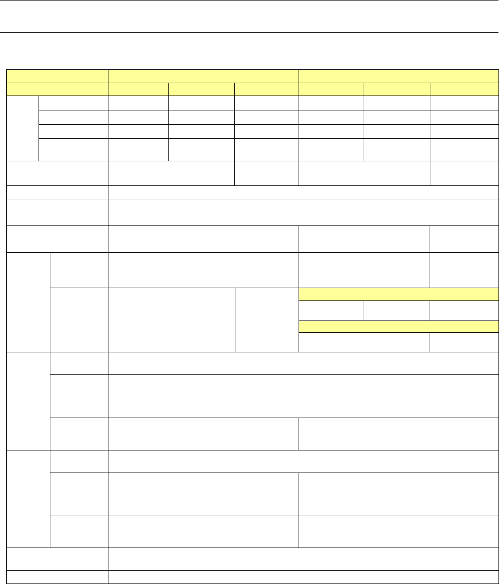
① Basic specifications
KE-3010
KE-3020V / KE-3020VR
Board specifications
M PWB
L PWB
XL PWB
M PWB
L PWB
XL PWB
Board
dimensi
ons
Standard
330×250 ㎜ 410×360 ㎜ 610×560 ㎜ 330×250 ㎜ 410×360 ㎜ 610×560 ㎜
L-Wide -
510×360 ㎜
- -
510×360 ㎜
-
Long PWB
650x250 ㎜ 800×360 ㎜ 1210×560 ㎜ 650x250 ㎜ 800×360 ㎜ 1210×560 ㎜
L-Wide(long
PWB)
-
1010×360 ㎜
- -
1010×360 ㎜
-
Board transport reference
position
Front reference
Rear reference
Front reference
Front reference
Rear reference
Front reference
Supported languages
English, Japanese and Chinese is selected in real time.
Conveyor height
900 ㎜±20 ㎜
950 ㎜±20 ㎜ (option, EN machine: standard)
Component height
SC(6 ㎜)
NC(12 ㎜)
NC(12 ㎜)
HC(20 ㎜)
EC(25 ㎜)
Componen
t
placement
speed
* See
Note
1, 2, and 4
.
Chip
component
(IPC9850)
18,500(CPH) 17,100(CPH) 15,300(CPH)
IC component
9,000(CPH)
* S
ee Note 3.
7,000 (CPH)
* S
ee Note 3.
KE-3020V(LNC60+IC head)
9,470(CPH) 9,350(CPH) 7,100(CPH)
KE-3020VR(LNC60)
9,000(CPH) 7,000(CPH)
Componen
t size
*
See Note
1.
Laser
recognition
0402~□33.5 ㎜ or opposite angle 47 ㎜
Image
recognition
(MNVC)
* See Note 3
Standard camera: □3~□33.5 ㎜
High-resolution camera (option): 1005~□20 ㎜
Image
recognition
(IC head)
-
Standard camera: □3~50×150 ㎜ or □74 ㎜
High-resolution camera: 1005~50×120 ㎜ or □48 ㎜
Placement
accuracy
*
See Note
1.
Laser
recognition
±50μm (Cpk≧1)
Image
recognition
(MNVC)
* See Note 3
±40μm ±40μm
Image
recognition
(IC head)
- ±30μm
Number of component to
be placed
A maximum of 160 types (when using EF08HD)
EN Specifications
Enable
* Note 1: For details of specifications, refer to Section 4-3 Placement cycle time, Section 4-5 Target
components, and Section 4-6 Placement accuracy.
For each specification of MNVC (option) of KE-3010, refer to Section 4-3, Section 4-5, and Section
4-6. which are aforementioned.
* Note 2: Transport: Front reference, Component height: 6 mm (KE-3010)/12 mm (KE-3020V/20VR M
specification/L specification)/25 mm (KE-3020V/20VR XL specification)
* Note 3: It is the approximate value when MNVC (option for KE-3010) is used and/or the components are
simultaneously picked up with 6 nozzles.
*Note 4: Except case of using the RF_ETF_Attachment.

- 9 -
② The relationship among the model names, recognition devices and heads is shown below.
KE-3010
KE-3020V
KE-3020VR
Explanation
LNC60 ○ ○ ○
This can place small-shape and thin chips at a
high speed by 6 nozzles.
IC
head
(CDS)
- ○ -
This head can place IC components of
large-shape QFP, CSP, BGA, etc. by vision
recognition.
IC
head
(FMLA)
- - ○
This head can place components by laser
recognition and vision recognition. All types of
nozzles such as gripper nozzle and particular
ordering nozzle can be used for the IC head
(FMLA).
VCS
-
* See
Note 1.
○ ○
VCS can perform vision recognition of IC
components. An optional high-resolution camera
can be added.
*Note 1: The standard camera is attached to MNVC (option). The high-resolution camera is
also attached.
③ Recognition function
KE-3010 KE-3020V KE-3020VR Explanation
MNVC Option
○ ○
Vision recognition can be performed by LNC60.
IC components of small-shape QFP, CSP, BGA,
etc. can be placed at a high speed. Vision
recognition can be performed by VCS in the
high-speed non-stop mode. (S-VCS)
- 10 -
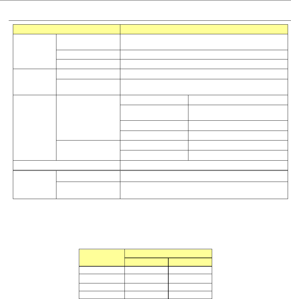
4.2. Mechanical/Electrical Specifications
4.2.1. Usage environment conditions
KE-3010/3020V/3020VR
Power supply
Voltage
Three-phase 200V, 220V, 240V, 380V, 400V, 415V AC ±10% (See
Note 1
)
Frequency 50/60Hz
Rated apparent power 2.2kVA
Air supply
Air pressure
0.5±0.05 MPa dry air
Maximum air
consumption
50L/min (ANR) (See Note 2)
Environment
requirements
During operation
Ambient temperature
+ 10 to + 35 °C
Placement accuracy
guarantee temperature
+ 20 to + 25 °C
Relative humidity
30 % to 80% RH (No condensation)
Altitude 1,000m or less
During transportation
or storage
Ambient temperature
- 15°C to + 70°C
Relative humidity
20 % to 95% RH (No condensation)
Noise
73 dB (A) or less (See Note 3)
Installation
conditions
(for a EN
machine)
Overvoltage category Category III according to IEC60664-1
Pollution degree Degree 3 according to IEC60664-1
Note 1: No power supply cable at the primary side is attached thereto.
We make NO WARRANTIES against any accident of the primary side wiring caused by
short–circuit of the power cable and so on. Please use a 5.5-mm
2
or more diameter of
power cable for each phase. (Note: the appropriate cross-section area of the cable varies
depending on the supplied power voltage and the length of the power cable.)
Cable length
(m)
Conductor cross section (mm
2
)
200Vseries 400Vseries
Less than 20 5.5 5.5
30 8.0 5.5
40
10.0
6.0
50
14.0
6.0
・Peak current (at AC200V 3phase power) : 40A
Note 2: ANR conditions are as follows:
Temperature = 20°C,
Absolute pressure = 0.1MPa (=100kPa=1bar),
Relative humidity = 65%
Note 3: This value was measured with conforming to the JIS Z8731 regulation.