KE-3010_SPE_EN - 第17页
- 12 - 4.3. Component place ment C y cle Ti me (The Number of Component to Be Placed Per Hour ) ① Laser recognition (Unit: CPH) KE - 3010 KE - 3020V/3020VR Reference ra il Front re ference Rear refer ence Front reference…
- 11 -
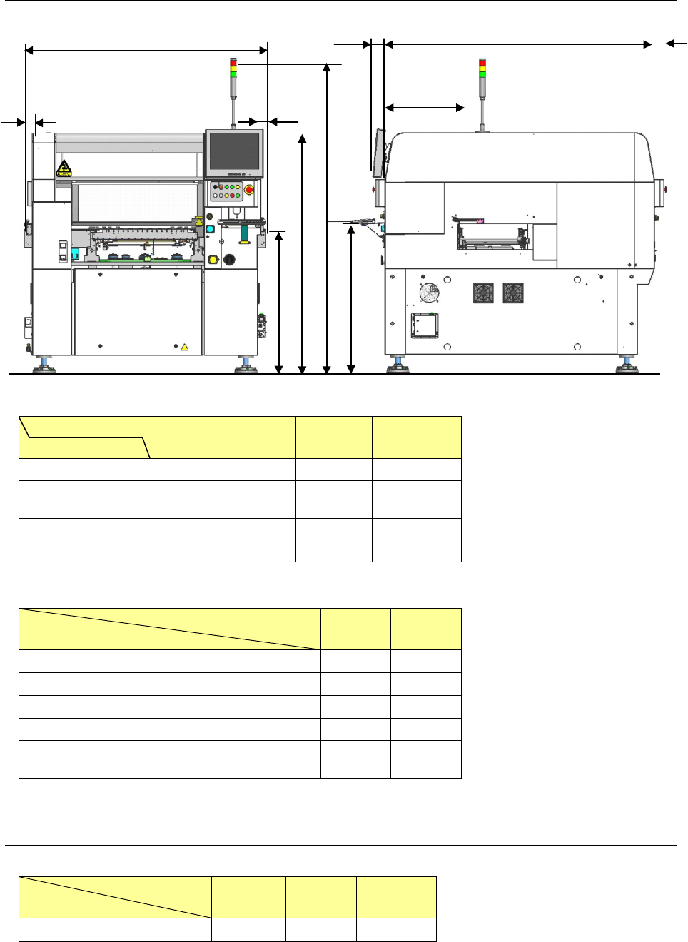
4.2.2. Outside dimension (except for the largest projections)
(Unit: mm)
PWB specification
Dimensions
M PWB L PWB L-Wide XL PWB
A (transport length) 1,500 1,500 1,800 2,131
C (depth:
excluding LCD)
1,580 1,690 1,690 1,890
H (transport output
amount)
50 50 200
228.6(L)
222.4(R)
* The tolerance of the above dimensions is ±15 mm.
(Unit: mm)
Transport height
Dimensions
900mm 950mm
B (Top surface of the transport belt from the floor) 900 950
D (Bottom of the keyboard from the floor) 936 986
E (Top surface of the cover from the floor) 1,500 1,550
G (Top surface of the signal light from the floor) 1,970 2,020
F (PWB transport path from the front side of the
cover)
484 484
* The tolerance of the above dimensions is ±5 mm.
4.2.3. Mass
(Unit: kg)
PWB specification
Model
M PWB L PWB XL PWB
KE-3010/3020V/3020VR 1,850 1,900 2,250
H
H
A
B
C
E
G
F
(90)
D
(90)
- 12 -
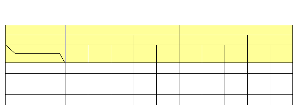
4.3. Component placement Cycle Time
(The Number of Component to Be Placed Per Hour)
① Laser recognition
(Unit: CPH)
KE-3010 KE-3020V/3020VR
Reference rail Front reference Rear reference Front reference Rear reference
PWB size
Component height
M L XL M L M L XL M L
6mm
18,500 18,500 18,500 17,500 15,500
- - - - -
12mm
17,100 17,100 17,100 16,500 15,000 17,100 17,100
-
16,500 15,000
20mm - - - - -
15,900 15,900
-
14,500 14,000
25mm
- - - - - - -
15,300
- -
*1: This is the number of components to be placed for one hour when 400 pieces of 0603 and 1005 capacitors
are placed onto a 200 mm x 200 mm board at an angle of 0, 90, 180 and 270 degrees sequentially. (This
method conforms to the IPC9850 regulation.)
*2: Electric feeders are used as a component supply device.
*3: KE-3020V and KE-3020VR place components in sequence by simultaneous pick-up of the 6 nozzles of the
LNC60 head.
*4: Since the 0402 components require to be placed in the particular sequence, when only the 0402
components are placed the placement cycle time is reduced to approximately half.
*5: For the rear reference, each value indicates the cycle time to be applied when components are placed from
a tape feeder attached on the front side.
*6: The cycle time will take longer by up to 3% when the placement monitor is used. In addition, when the
setting “The system pauses if a component existence error occurs” is enabled, the cycle time will take
longer by up to 30%.
- 13 -
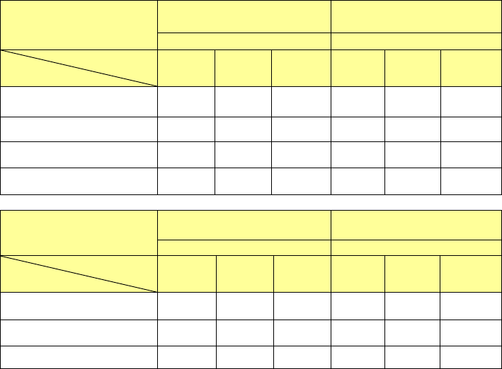
② Image recognition
(Unit: CPH)
Head
KE-3020V
KE-3020VR
KE-3010
(
MNVC
)
LNC60
+
IC head
LNC60
PWB size
Supply form
M L XL M L XL
Feeder simultaneous
pickup
9,470 9,350 7,100 9,000 9,000 7,000
DTS 5,100 5,100 4,000 5,100 5,100 4,000
MTS(TR5SNX) 5,100 5,100 4,000 5,100 5,100 4,000
MTC(TR6SNV) 1,300 1,300 1,100 1,300 1,300 1,100
Head
KE-3020V
KE-3020VR
KE-3010(MNVC)
IC head(1 nozzle)
LNC60 (1 nozzle)
PWB size
Supply form
M L XL M L XL
DTS 2,400 2,400 2,000 2,400 2,400 2,000
MTS(TR5SNX) 2,300 2,300 1,900 2,300 2,300 1,900
MTC(TR6SNV) 1,300 1,300 1,100 1,300 1,300 1,100
*1: This is the number of components to be placed for one hour when 36 pieces of QFP and BGA whose outer
dimension is 10 mm x 10 mm or less are placed onto a 330 mm x 250 mm board at an angle of 0, 90, 180
and 270 degrees sequentially.
*2
:
For a tape feeder, it indicates the placement cycle time to be applicable when lead components whose outer
dimensions are 10 mm x 10 mm or less are placed from a tape feeder attached on the rear side.
*3: Component height is 12 mm for M and L machine and 25mm for XL machine.
*4: The time for ATC replacement, board transport and BOC mark recognition is excluded.