KE-3010_SPE_EN - 第19页
- 14 - 4.4. N ozzle s V arious types of noz zles hav e been designe d to incr ease the reli ability of placement of each ty pe of component s a s shown i n the t able below . Y ou can select one of t he nozz le sets show…
- 13 -
② Image recognition
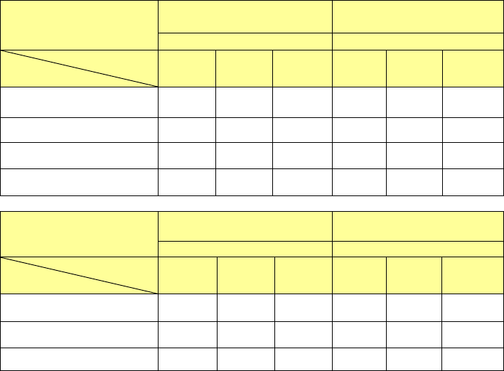
(Unit: CPH)
Head
KE-3020V
KE-3020VR
KE-3010
(
MNVC
)
LNC60
+
IC head
LNC60
PWB size
Supply form
M L XL M L XL
Feeder simultaneous
pickup
9,470 9,350 7,100 9,000 9,000 7,000
DTS 5,100 5,100 4,000 5,100 5,100 4,000
MTS(TR5SNX) 5,100 5,100 4,000 5,100 5,100 4,000
MTC(TR6SNV) 1,300 1,300 1,100 1,300 1,300 1,100
Head
KE-3020V
KE-3020VR
KE-3010(MNVC)
IC head(1 nozzle)
LNC60 (1 nozzle)
PWB size
Supply form
M L XL M L XL
DTS 2,400 2,400 2,000 2,400 2,400 2,000
MTS(TR5SNX) 2,300 2,300 1,900 2,300 2,300 1,900
MTC(TR6SNV) 1,300 1,300 1,100 1,300 1,300 1,100
*1: This is the number of components to be placed for one hour when 36 pieces of QFP and BGA whose outer
dimension is 10 mm x 10 mm or less are placed onto a 330 mm x 250 mm board at an angle of 0, 90, 180
and 270 degrees sequentially.
*2
:
For a tape feeder, it indicates the placement cycle time to be applicable when lead components whose outer
dimensions are 10 mm x 10 mm or less are placed from a tape feeder attached on the rear side.
*3: Component height is 12 mm for M and L machine and 25mm for XL machine.
*4: The time for ATC replacement, board transport and BOC mark recognition is excluded.
- 14 -
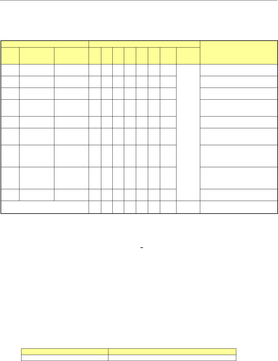
4.4. Nozzles
Various types of nozzles have been designed to increase the reliability of placement of each type
of components as shown in the table below.
You can select one of the nozzle sets shown in Table 1: as the standard nozzles supplied.
Table 1 Nozzles supplied as the standard devices
Nozzle
Nozzle assembly
Applicable components
(reference) and remarks
NO.
Internal
diameter of a
nozzle
External
diameter of a
nozzle
A B D E F G H
Std.
Nozzle
Select
500
2-φ0.4 1.0 x 0.5 − 6 − − − − −
* See
Note 1
1005, 1608, 2012 *See Note2
SOT (Molding: 1.6 x 0.8)
501
φ0.25 0.7 x 0.4 − − 6 − − −
0603
502
φ0.4 φ0.7 6 − 6 3 − − 3
1005
503
φ0.6 φ1.0 6 − 3 6 3 6 3
1608, 2012, SOT (Molding:
1.6 x 0.8), SOT (Molding: 2.0
x 1.25)
504
φ1.0 φ1.5 − 4 1 3 6 6 3
2012, 3216, SOT23, SOT
(Molding: 2.0 x 1.25)
505
φ1.7 φ3.5 1 2 − 3 3 1 3
Aluminum electrolytic capacitor
(small), tantalum electrolytic
capacitor, trimmer
506
φ3.2 φ5.0 1 1 − 1 3 1 3
Aluminum electrolytic capacitor
(medium),
SOP (narrow type),
SOJ, Connector
507
φ5.0 φ8.5 1 1 − − 1 1 1
Aluminum electrolytic capacitor
(large),
SOP (wide type),
TSOP, QFP, PLCC, Connector
508C
φ8.0 φ9.5 1 1 1 1 1 1 1
QFP, PLCC, BGA
Total number of nozzles 16 15 17 17 17 16 17 15
* Total number of nozzles that can be installed onto an ATC station: 36 pieces (Standard nozzles 34
pieces and up to large-size standard nozzles 2 pieces)
Note 1 As a Std. Nozzle Select, you can select 15 nozzles among those whose number is from 500 to 508C.
However, you have to select a nozzle to be used for calibration of the machine:
・ For laser calibration (one of the nozzles choose from 500, 502 and 503)
・ For image calibration (508C nozzle)
Note 2 Since a theta error may occur due to the shape of the surface of a 2012R component to be picked up
(such as differences of manufactures and/or resistance values), use a No. 504 nozzle if you have to
place 2012R components in the high density (the gap between the adjacent components: 0.3 mm or
less).
Limitation on nozzles to be used
(1) Limitation on nozzles used on the LNC60
The LNC60 head cannot be used together with a large nozzle.
(2) Limitation on nozzles used on the IC head side of KE-3020V
The IC head of KE-3020V is intended for components of □ 3mm or more. Accordingly,
the following nozzles cannot be used because their nozzle ends are thin. (The IC head
(FMLA) of KE-3020VR has no limitation for use (except the 509 nozzle)).
Nozzle No. under limitation for use
Standard nozzle
500, 501, 502, 503
Optional nozzles
Other nozzles than the nozzle attached as standard are optional. In addition to the nozzle
dedicated for 0402 (509 nozzle), nozzles matched to different-shape components are
prepared. For details, please ask JUKI sales or dealer.
- 15 -
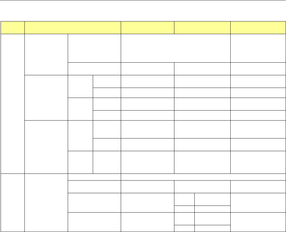
4.5. Applicable Component
(1) Component size and component height Unit: mm
KE-3010 KE-3020V /3020VR
MNVC
(option for KE-3010)
Length x
width,
component
dimensions
Laser recognition
LNC60
*The number of nozzles or
pickup components varies
depending on component
dimensions.
(Note 1)
0.4 x 0.2 to □33.5 or opposite angle length 47 mm
(See Note 6.)
-
FMLA
(KE-3020VR only)
- 1.0×0.5~□33.5 -
Overall vision
recognition
(Note 2) (Note 8)
Standard
camera
(visual field
54 mm)
Reflection - □3.0~□50.0
□3.0~□33.5
(Note 6)
Transmission
- □3.0~□50.0 □3.0~□6.0
High-resoluti
on camera
visual field
27 mm)
Reflection -
1.0×0.5~□24.0
(Note 3) (Note 4)
1.0×0.5~□20.0
(Note 4) (Note 7)
Transmission
- □3.0~□24 □3.0~□6.0
Vision sectional
recognition
(Note 2) (Note 8)
Standard
camera
(visual field
54 mm)
Reflection -
Maximum:
50×150(1 x 3-split)
□74(2 x 2-split)
Not applicable
Transmission
-
Maximum:
50
×
120
(
1 x 3-split
)
Not applicable
High-resoluti
on camera
(visual field
27 mm)
Reflection -
24×72(1 x 3-split)
□48(2 x 2-split)
Not applicable
Component
height
The maximum height
varies depending on
the machine
specifications.
SC(T=6mm)
NC(T=12mm)
HC(T=20mm)
EC(T=25mm)
LNC60
0.08 (for 0402) to T
FMLA
(KE-3020VR only)
- 0.3~T -
VCS overall recognition -
CDS
0.4~T
(Note 5)
0.08~T
FMLA 0.1~T
VCS sectional recognition -
CDS
0.4~T
(Note 5)
Not applicable
FMLA 0.1~T
Note 1 The maximum size of components that can be recognized with 6 nozzles of the LNC60 at the same time is □ 10.0 mm. When placing
components exceeding □10 mm by LNC60 head, only 3 nozzles are used for pickup.
When you are to place components whose size is more than □ 10.0 mm with the LNC60 head, only three heads are used to pick them up.
Note 2 The minimum dimensions of the mold should be □ 1.7 mm or more. The described maximum dimensions of a component should be
applicable if a pick-up error of the XY dimensions is ± 1 mm or less and the angle error is ± 3° or less.
Note 3 When the dimensions of a component are less than □ 3 mm, an NC60 head is used to recognize it and place it on a board. (Available with
a KE-3020V only)
Note 4 When you want to recognize image of components: a resistor chip, trimmer, SOT or LED whose size is from 1.0 × 1.0 to □ 3 mm,
recognize such a component as a general-purpose vision component.
Note 5 The minimum component height has no effect on VCS recognition but the component height shall be recognizable with a CDS
(component drop check sensor)(KE-3020V only).
Note 6 When Components from □20 mm to □33.5 mm are to be handled with a multi-laser head, they are picked up with an L3 head or L4 head.
Note 7 Component with the size of 24.0 mm x 11.0 mm is available even though the length is more than 20mm.
Note 8 The mass of a component that can be placed on a board with an IC head is as follows since the stable adsorption face has to be
maintained:
・Component with the size of 50 mm x 50 mm: Batch image recognition: 40g or less Divided image recognition: 35g or less
・Component with the size of 50 mm x 150 mm: 17g or less