KE-3010_SPE_EN - 第2页
Impor tant (1) No part of this document may be copied or reproduced w ithout the prior permission of JUKI Corporation. (Including so ftware and program) (2) The contents of this document are subject to change w ithout no…
High-Speed Chip Shooter
KE-3010
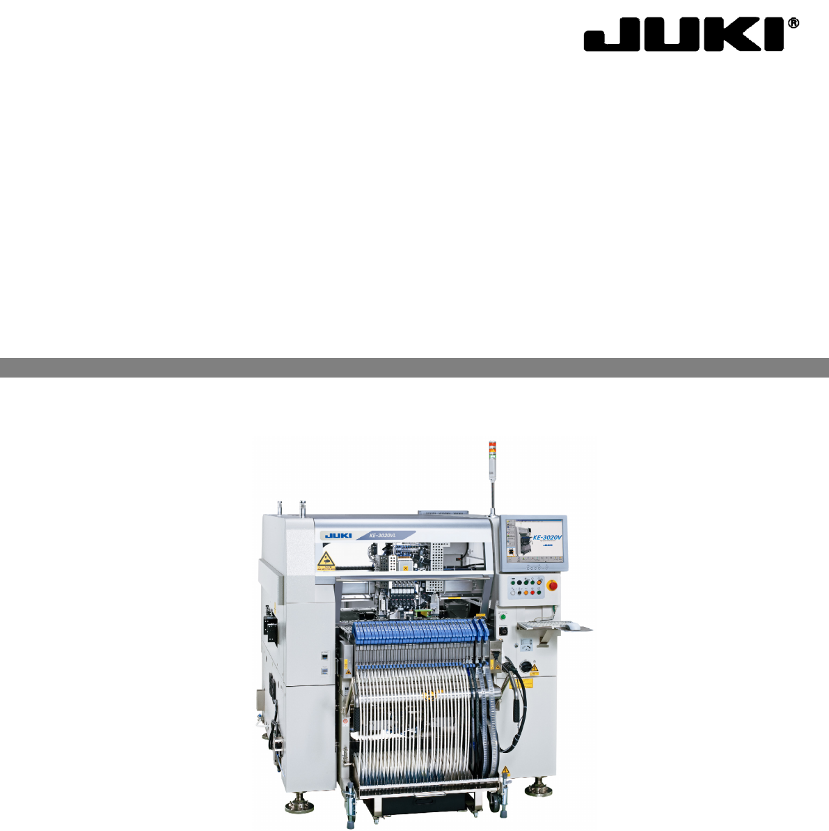
High-Speed Flexible Mounter
KE-3020V/3020VR
PRODUCT SPECIFICATIONS

Important
(1) No part of this document may be copied or reproduced without the prior
permission of JUKI Corporation. (Including software and program)
(2) The contents of this document are subject to change without notice.
(3) This manual is prepared with extreme care. However, if you have any question
or find any error or omission in writing, contact our dealer or JUKI Corporation.
(4) JUKI Corporation shall disclaim all the responsibility for any trouble resulting
from the user's abnormal operation regardless of Item (3).
(5) Microsoft, Windows are registered trademarks or trademarks of Microsoft
Corporation in the United States and /or other countries.
The company names and product names mentioned in this document are
generally registered trademarks or trademarks of the respective companies.
Table of contents
1. Introduction ....................................................................................................................................... 1
1.1. General ................................................................................................................................... 1
1.2. Model variations ..................................................................................................................... 1
2. Features ........................................................................................................................................... 2
3. System Configuration Table ............................................................................................................. 5
4. Specifications ................................................................................................................................... 8
4.1. Features of each model .......................................................................................................... 8
4.2. Mechanical/Electrical Specifications .................................................................................... 10
4.2.1. Usage environment conditions ................................................................................ 10
4.2.2. Outside dimension (except for the largest projections) ........................................... 11
4.2.3. Mass ........................................................................................................................ 11
4.3. Component placement Cycle Time
(The Number of Component to Be Placed Per Hour) .................................................... 12
4.4. Nozzles ................................................................................................................................. 14
4.5. Applicable Component ......................................................................................................... 15
4.6. Component Placement Accuracy ......................................................................................... 16
4.7. Applicable PWBs .................................................................................................................. 17
4.7.1. PWBs transport direction ......................................................................................... 17
4.7.2. PWB sizes and Mass............................................................................................... 17
4.7.3. Unavailable areas for placing components on the board ........................................ 18
4.7.4. Support pin installation disable range ..................................................................... 20
4.7.5. Placement enable range on the top and bottom surfaces of PWB ......................... 22
4.7.6. Function correcting the PWB positions ................................................................... 23
5. Standard Functions And Optional Functions ................................................................................. 26
5.1. Standard ...............................................................................................................................
26
5.1.1. Multi Nozzle Vision Centering (MNVC: Option for KE-3010) .................................. 26
5.1.2. Height Measurement System (HMS) ...................................................................... 28
5.1.3. Vacuum pump ......................................................................................................... 28
5.1.4. Feeder Float Detecting Sensor ............................................................................... 28
5.1.5. Component database .............................................................................................. 28
5.2. Option ................................................................................................................................... 29
5.2.1. Bad mark reader (Bad Mark Reader/BMR factory-set option) ................................ 29
5.2.2. Feeder overall change table system (factory-set option) ........................................ 29
5.2.3. None-stop operation (factory-set option) ................................................................. 29
5.2.4. Component verification
(Component Verification System/CVS factory-set option) .................................. 30
5.2.5. SOT Direction Check Function (Factory-Set Option) .............................................. 30
5.2.6. Simple load control function (Factory-Set Option) .................................................. 31
5.2.7. Rear Side Operation Unit (Factory-Set Option) ...................................................... 31
5.2.8. Feeder position indicator (Feeder Position Indicator/FPI factory-set option) ......... 31
5.2.9. High resolution camera (Factory-Set Option) ......................................................... 32