KE-3010_SPE_EN - 第23页
- 18 - 6 mm (Pin diameter + 2 .0 mm) *1 6 mm (Pin diameter + 2.0 mm) *1 4.7.3. Unavailable areas for placing components on the board *1: W hen you select the pin dia meter fr om 1.8 mm to 2.0mm or f rom 2.5 m m to 4.0 mm…
- 17 -
4.7. Applicable PWBs
4.7.1. PWBs transport direction
Rightward flow (transporting from left to right, looking from the front side)
Leftward flow (transporting from right to left, looking from the front side)
Note
:
This direction is set at the factory (Factory-set).
4.7.2. PWB sizes and Mass
(1) PWB sizes
(Unit: mm)
Minimum size (D
1
x W
1
) Maximum size (D
2
x W
2
) Thickness T
M PWB
specification
50×30
(When the auto PWB width
adjusting function is provided:
50 x 50)
330×250
(When a function applicable to
long PWB is provided: 650 x
250)
0.3~4.0
L-PWB
specification
410×360
(When a function applicable to
long PWB is provided:
800 x 360)
L-Wide
specification
510×360
(When a function applicable to
long PWB is provided:
1010 x 360)
XL-PWB
specification
610×560
(When a function applicable to
long PWB is provided:
1210 x 560)
Note 1: “D” indicates the dimension in the board transport direction, and “W” indicates the direction
perpendicular with “D” W/D should be 2 or less.
Note 2: Contact us for a notched board or board whose shape is irregular.
Note 3: A PW B whose reflection ratio is low may not be able to be detected regardless of its material
or color.
(2) Maximum allowance of PWB mass :2,000 g
(3) Allowable warpage of a PWB
0.2 mm or less per 50 mm area, and 1 mm or less for both upper and lower directions
(these values conform to the JIS B 8461 regulation.)
- 18 -
6 mm (Pin diameter + 2.0 mm) *1
6 mm (Pin diameter + 2.0 mm) *1
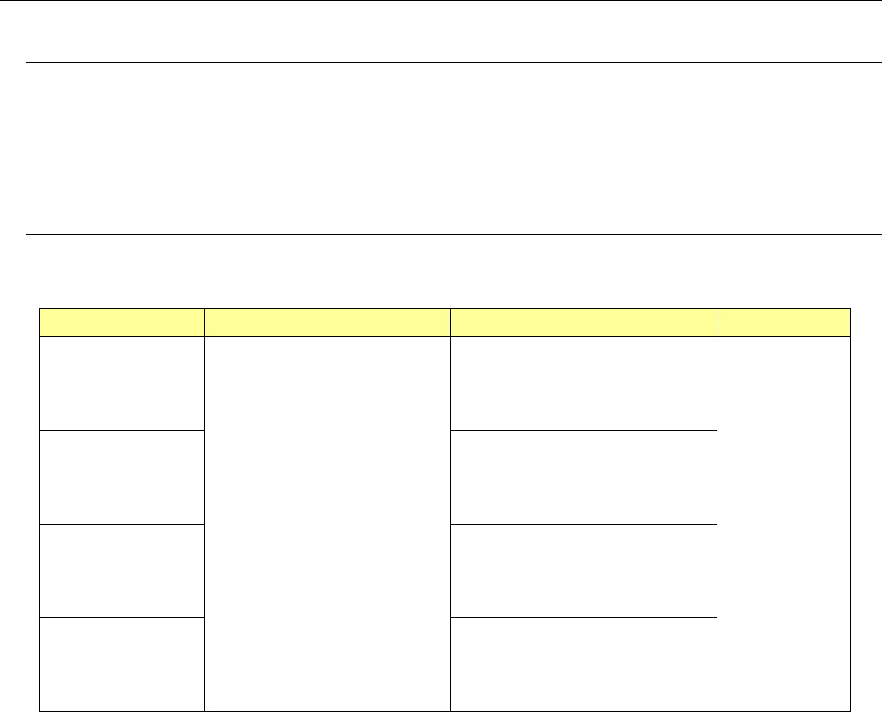
4.7.3. Unavailable areas for placing components on the board
*1: When you select the pin diameter from 1.8 mm to 2.0mm or from 2.5 mm to 4.0 mm, any component cannot
be placed in the area including the pin diameter plus 2 mm. (This rule shall be applied to the following
board type.)
M PWB specification
PWB transport direction
Placement disable range
3mm
5±0.1mm
50
~
330mm
3mm
30
~
250mm
50 to 250 mm for the auto PWB width adjusting function
Transport rail fixed side
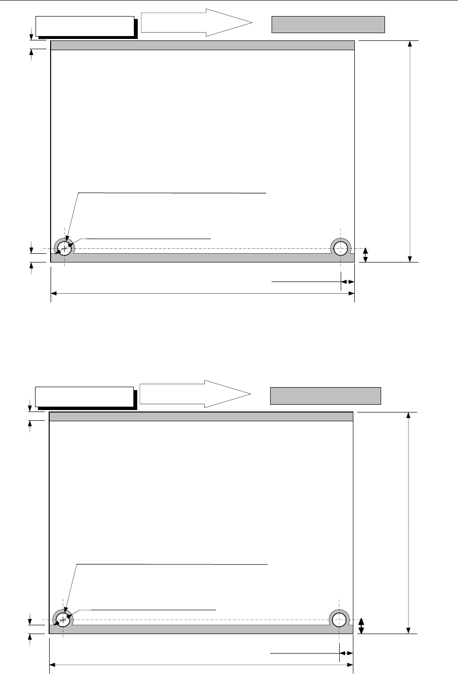
PWB transport direction
Placement disable range
3mm
5±0.1mm
50
~
410mm
3mm
30
~
360mm
50 to 250 mm for the auto PWB width adjusting function
Transport rail fixed side
L PWB specification
5±0.1mm
5±0.1mm
When the diameter of the reference pin is 4 mm
When the diameter of the reference pin is 4 mm
- 19 -
6 mm (Pin diameter + 2.0 mm) *1
PWB transport direction
Placement disable range
3mm
5±0.1mm
50
~
610mm
3mm
30
~
560mm
50 to 250 mm for the auto PWB width adjusting function
Transport rail fixed side
XL PWB specification
5±0.1mm
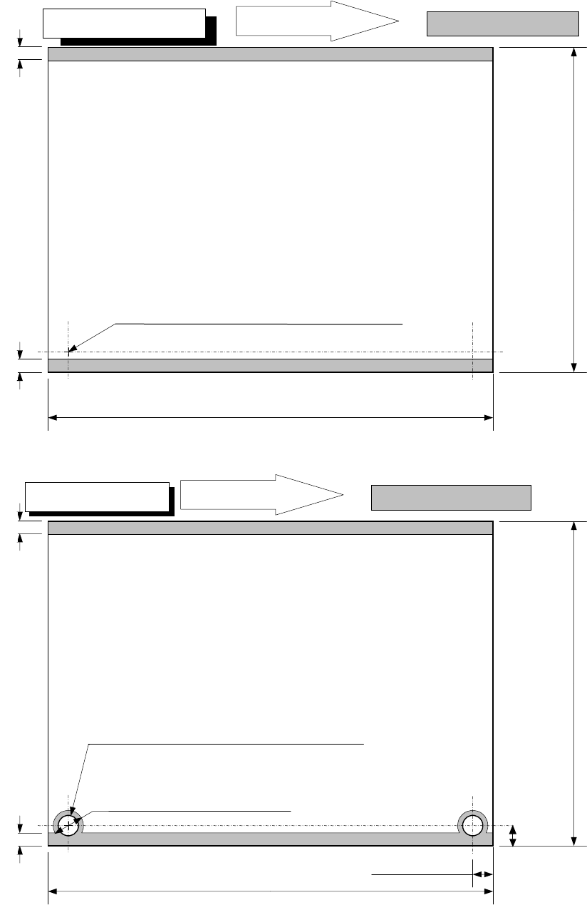
L-Wide PWB specification
PWB transport direction
Placement disable range
3mm
50
~
510mm
3mm
30
~
360mm
50 to 250 mm for the auto PWB width adjusting function
Transport rail fixed side
For L-Wide, the pin standard is not available.
When the diameter of the reference pin is 4 mm