KE-3010_SPE_EN - 第25页
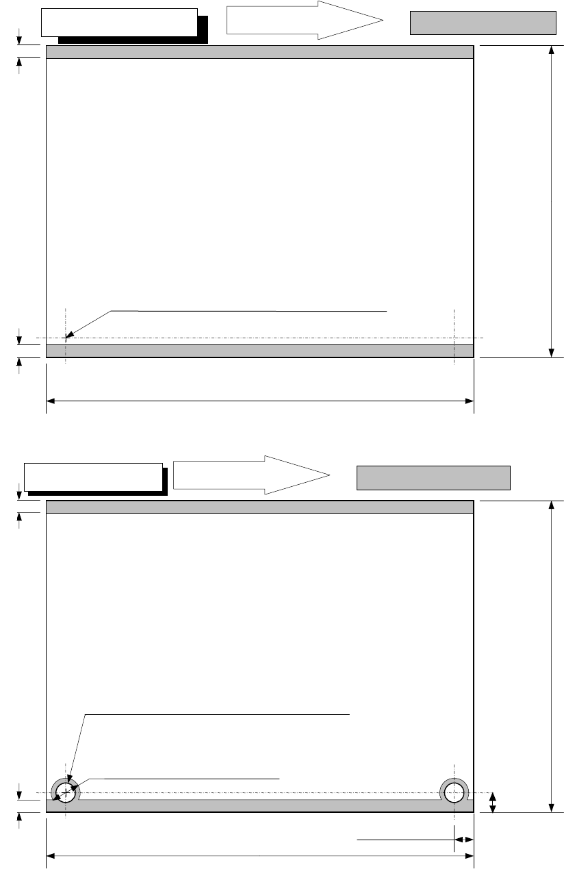
- 20 - 4.7.4. Support pin instal lation disable range These dim ensions are factor y - set ones. T he restriction range is added when the reference pin is used. The PW N transport direction is for a cloc kwise flow as sh…
- 19 -
6 mm (Pin diameter + 2.0 mm) *1
PWB transport direction
Placement disable range
3mm
5±0.1mm
50
~
610mm
3mm
30
~
560mm
50 to 250 mm for the auto PWB width adjusting function
Transport rail fixed side
XL PWB specification
5±0.1mm
L-Wide PWB specification
PWB transport direction
Placement disable range
3mm
50
~
510mm
3mm
30
~
360mm
50 to 250 mm for the auto PWB width adjusting function
Transport rail fixed side
For L-Wide, the pin standard is not available.
When the diameter of the reference pin is 4 mm
- 20 -
4.7.4. Support pin installation disable range
These dimensions are factory-set ones. The restriction range is added when the reference
pin is used. The PWN transport direction is for a clockwise flow as shown in the figure. In
the case of a flow in the opposite direction, the support pin disable range is bisymmetrical to
the figure.
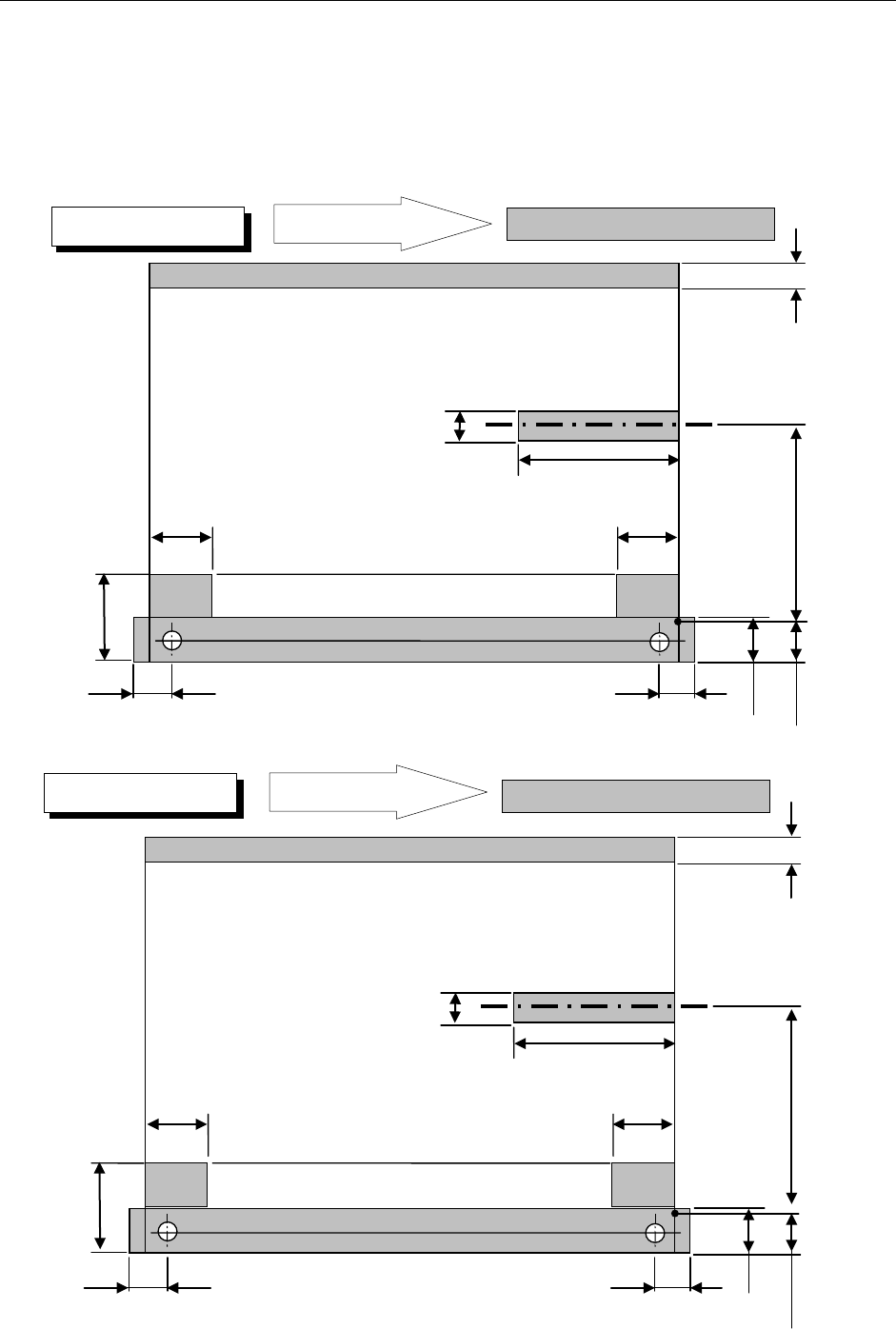
・PWN bottom drawing
26mm
39.3mm
26.5mm
61mm
26mm
26.5mm
20mm
23mm
22.6mm
0 to 292 mm Moving part
4.5mm
Placement disable range
PWB transport direction
Placement disable range
26mm
39.3mm
26.5mm
61mm
26mm
26.5mm
20mm
23mm
22.6mm
0 to 187 mm Moving part
4.5mm
Placement disable range
PWB transport direction
Placement disable range
M PWB specification
L PWB specification
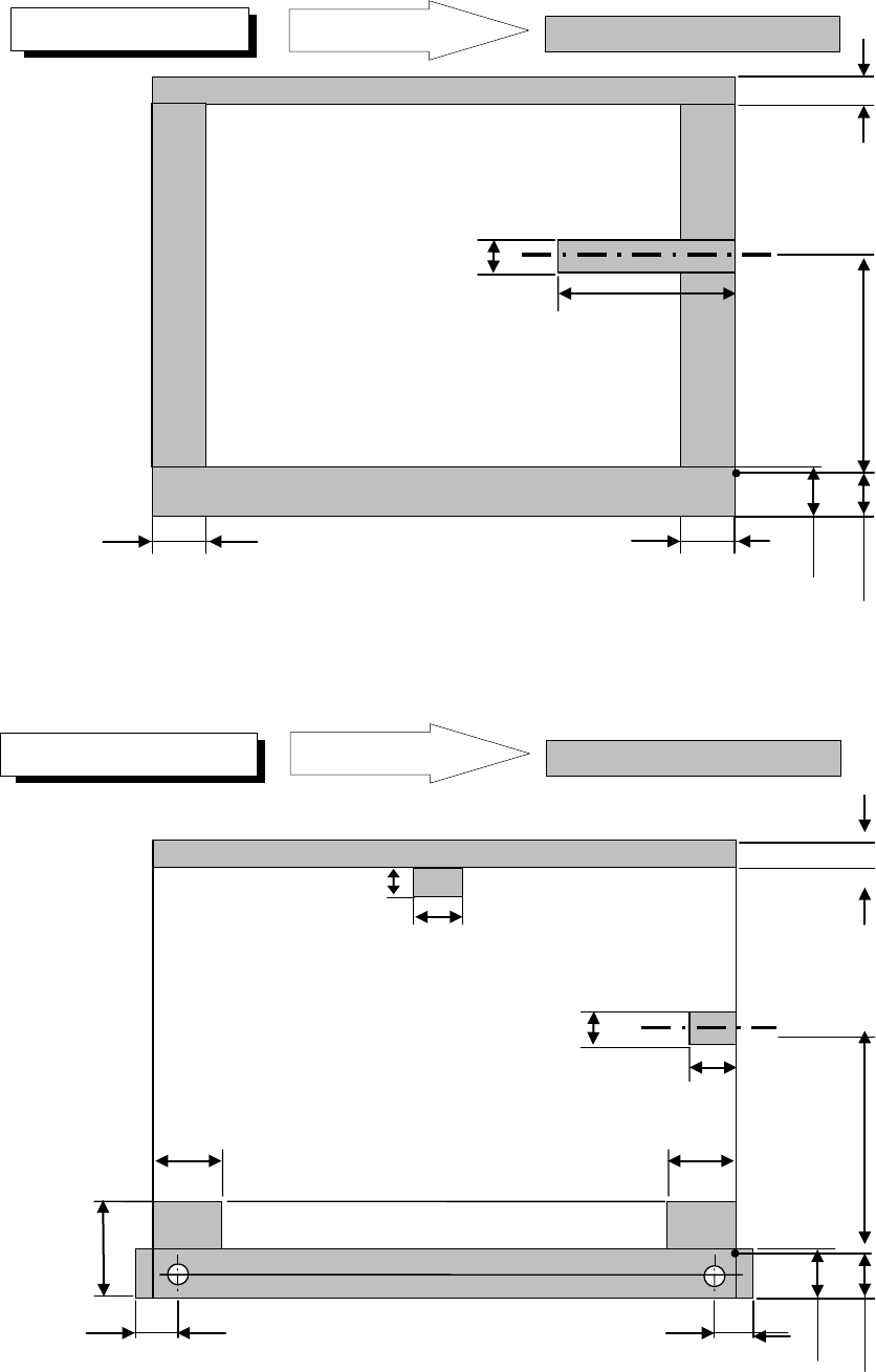
- 21 -
* For the L-Wide PWB specification, any pin reference option cannot be selected.
PWB transport direction
Placement disable range
61mm
20mm
22.6mm
0 to 292 mm Moving part
4.5mm
Placement disable range
PWB transport direction
Placement disable range
24.5mm
24.5mm
23mm
L-Wide PWB specification
XL Wide PWB specification
26mm
39.3mm
26.5mm
13mm
26mm
26.5mm
20mm
23mm
22.6mm
0 to 280.6 mm Moving part
6.5mm
Placement disable range
18.5mm
28mm