KE-3010_SPE_EN - 第30页
- 25 - Dimensions and tol erances The outside dimensions shall range from 0.5 mm up to 3.0mm, w hose tolerance, less than 10%. For all the inside - blank forms, the ed ging line width shall be more than 0.2 m m. Figur e …
- 24 -
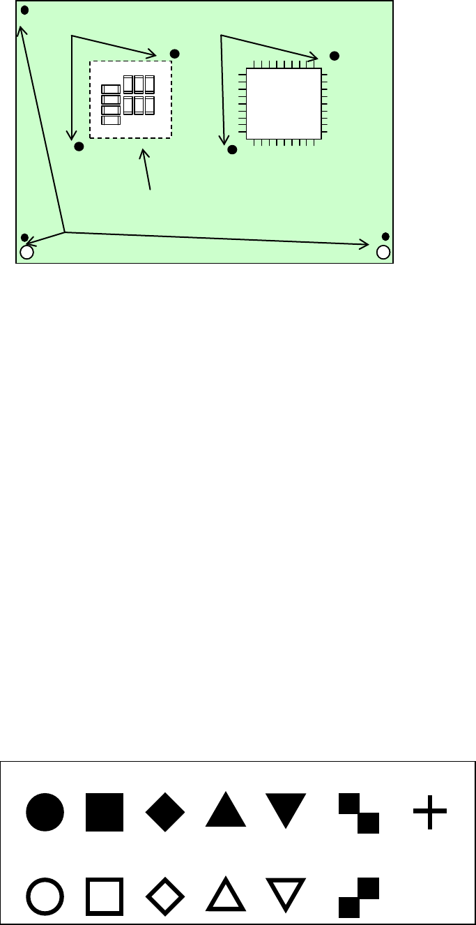
Figure Reference marks and components positioning marks
Basic quality of recognition marks
- Copper not coated or coated
- It needs to have a clear contrast between the recognition mark surface and the print
wiring quality.
- It needs to have neither oxidation nor quality deterioration of the recognition marks.
Coating the recognition marks
The recognition mark surfaces shall all be coated as follows:
- Transparent antioxidant coating - Solder plating
- Nickel plating - Gold plating
- Tin plating - Hot air repeller solder coating
Marking forms
- The standard marks represent the thirteen (13) forms as shown in the following block,
“Forms of Recognition Marks.”
- For any mark other than those shown in the said block, customers shall make templates
to allow for recognition through a pattern matching.
Note 1: Up to three PWB reference marks and up to six component placement area
positioning marks are supported.
Note 2: Within a field of vision, there should be no similar form pattern other than the
subjected form patterns.
- For regular triangles, checker patterns and users’ templates, the 90°up-side-down
marks can also be recognized.
Circle
Square
Diamond
Regular
triangle
Up-side-down
triangle
Checker
pattern
Cross
Inside-blank
circle
Inside-blank
square
Inside-blank
diamond
Inside-blank
up-side-down
triangle
Checker
pattern
Inside-blank
Regular
triangle
Figure Forms of Recognition Marks
The recognition marks shall all comply with EIAJ ET-7302 “Recognition marks for on-surface
placed PWBs.”
Component placement
area positioning marks
Component positioning
marks
Placement group
PWB reference marks
- 25 -
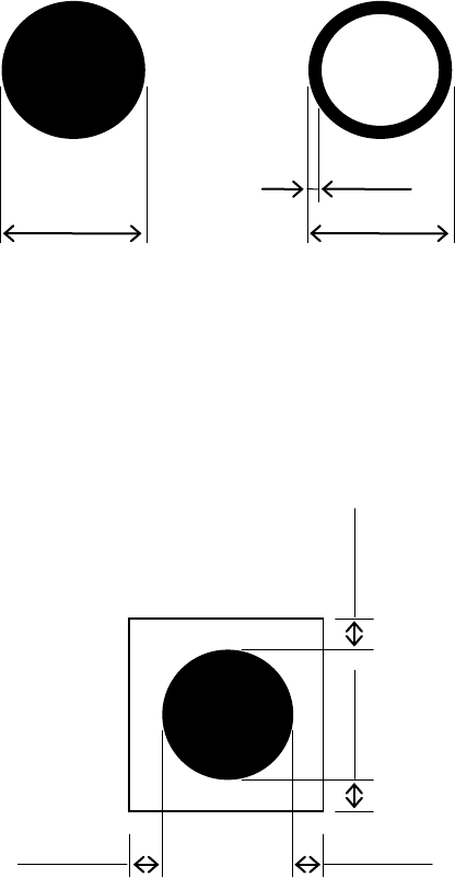
Dimensions and tolerances
The outside dimensions shall range from 0.5 mm up to 3.0mm, whose tolerance, less than
10%.
For all the inside-blank forms, the edging line width shall be more than 0.2 mm.
Figure Dimensions and tolerances of recognition marks.
It is desirable that there is, around each recognition mark, a space having nothing of such
other marks as conductor pattern, solder resist, marking and the like, and that this space
dimensions is a larger square than the mark by 0.5 mm or more from the outer
circumference of the recognition marks.
Figure Clearances of recognition marks
0.5 to
3.0mm
0.5 to 3.0mm
0.2 mm or
more
0.5 mm or more
0.5 mm or more
0.5 mm or more
0.5 mm or more
- 26 -
5.
Standard Functions And Optional Functions
5.1. Standard
5.1.1. Multi Nozzle Vision Centering (MNVC: Option for KE-3010)
In addition to the IC head, this function recognizes and places components picked up by
LNC60 head, and you can use the MNVC to perform various operations such as recognition
of a general-purpose vision component and coplanarity check (when the coplanarity check
option is selected).
Use of the MNVC greatly improves the productivity of a PWB on which many small
vision-centered components are to be placed.
Applicable component dimensions
(Unit: mm)
Recognizing method
VCS type
Lighting type
Component size
VCS overall recognition
Standard camera
(visual field 54 mm)
Reflection
□
3.0
~
□
33.5
(□3.0 to □10.0 for simultaneous
pickup using 6 nozzles)
Transmission
□
3.0
~
□
6.0
High-resolution
camera
(visual field 27 mm)
Reflection
1.0
×
0.5
~
□
20.0
(□3.0 to □10.0 for simultaneous
pickup using 6 nozzles)
Transmission
□
3.0
~□
6.0
Note 1: Any LNC60 cannot be used to recognize a component by dividing its image.
Note 2: The component height, lead pitch, ball pitch and ball diameter that can be recognized by the
L head are same as those that can be recognized by the R head.
Note 3
The maximum component size of □33.5 mm can be placed by L3/4 head only. The
L1/2/5/6 head is applicable to the maximum component size □20.0.Even if the size
exceeds □20.0, 24 x 11 mm is applicable.
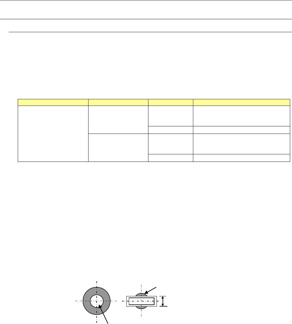
Applicable nozzles
− Standard nozzles: The number. 500 to 508C nozzles are applicable. Be sure that the
number. 505, 506, 507 and 508C nozzles shall be antidazzle.
− Customized nozzles: The section of any customized nozzle that is used to pick up a
component should not gleam when it is shot with a VCS except the area ± 2.0 mm from
the center of the nozzle.
High-Speed Non-stop vision recognition (S-VCS)
This function recognizes an image of a component with a VCS without stopping, and can
recognize and place IC components and other components at a high speed. (S-VCS)
Components equal to or smaller than a □10 mm component can be picked up, and/or
recognized without stopping with all heads (LNC60 head and IC head). Although the
number of nozzles used with an LNC60 head is restricted when components whose size
exceeds a □10 mm component are picked up, they can be recognized without stopping.
Note that they cannot be recognized without stopping under the following conditions.
The diameter of this gleaming area should be 4 mm or smaller.
This area should not gleam.
The width should be 4 mm or narrower.