KE-3010_SPE_EN - 第32页
- 27 - *C o nditions under w hich components will not be recognized at high speed without stoppin g The following com ponent s will not be recognized at hi gh speed without stopping: - G eneral - purpose v ision componen…
- 26 -
5.
Standard Functions And Optional Functions
5.1. Standard
5.1.1. Multi Nozzle Vision Centering (MNVC: Option for KE-3010)
In addition to the IC head, this function recognizes and places components picked up by
LNC60 head, and you can use the MNVC to perform various operations such as recognition
of a general-purpose vision component and coplanarity check (when the coplanarity check
option is selected).
Use of the MNVC greatly improves the productivity of a PWB on which many small
vision-centered components are to be placed.
Applicable component dimensions
(Unit: mm)
Recognizing method
VCS type
Lighting type
Component size
VCS overall recognition
Standard camera
(visual field 54 mm)
Reflection
□
3.0
~
□
33.5
(□3.0 to □10.0 for simultaneous
pickup using 6 nozzles)
Transmission
□
3.0
~
□
6.0
High-resolution
camera
(visual field 27 mm)
Reflection
1.0
×
0.5
~
□
20.0
(□3.0 to □10.0 for simultaneous
pickup using 6 nozzles)
Transmission
□
3.0
~□
6.0
Note 1: Any LNC60 cannot be used to recognize a component by dividing its image.
Note 2: The component height, lead pitch, ball pitch and ball diameter that can be recognized by the
L head are same as those that can be recognized by the R head.
Note 3
The maximum component size of □33.5 mm can be placed by L3/4 head only. The
L1/2/5/6 head is applicable to the maximum component size □20.0.Even if the size
exceeds □20.0, 24 x 11 mm is applicable.
Applicable nozzles
− Standard nozzles: The number. 500 to 508C nozzles are applicable. Be sure that the
number. 505, 506, 507 and 508C nozzles shall be antidazzle.
− Customized nozzles: The section of any customized nozzle that is used to pick up a
component should not gleam when it is shot with a VCS except the area ± 2.0 mm from
the center of the nozzle.
High-Speed Non-stop vision recognition (S-VCS)
This function recognizes an image of a component with a VCS without stopping, and can
recognize and place IC components and other components at a high speed. (S-VCS)
Components equal to or smaller than a □10 mm component can be picked up, and/or
recognized without stopping with all heads (LNC60 head and IC head). Although the
number of nozzles used with an LNC60 head is restricted when components whose size
exceeds a □10 mm component are picked up, they can be recognized without stopping.
Note that they cannot be recognized without stopping under the following conditions.
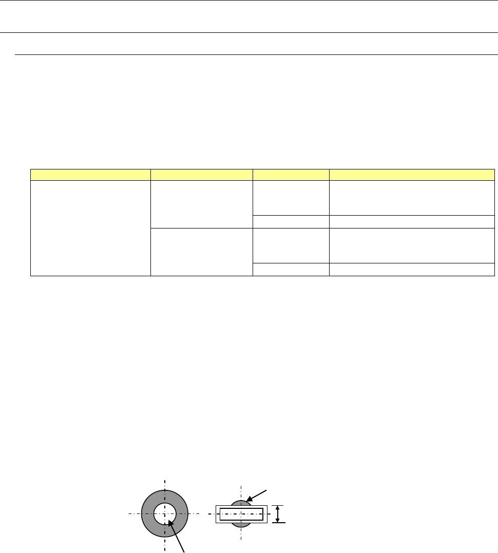
The diameter of this gleaming area should be 4 mm or smaller.
This area should not gleam.
The width should be 4 mm or narrower.
- 27 -
*Conditions under which components will not be recognized at high speed without stopping
The following components will not be recognized at high speed without stopping:
- General-purpose vision components other than “lead components containing three or
less element groups and two or more elements on the outer lead or inner lead”
- Components that will be recognized with the transmission type lighting
- Components whose size exceeds □33.5 mm
- Components whose XY speed is set to “Low” or lower
- Components whose recognition center offset is already set
- Components whose image is to be divided to be recognized
If the existing recognizing method is advantageous to the placement tact, high-speed
non-stop recognition is not performed.

- 28 -
5.1.2. Height Measurement System (HMS)
When preparing the pick-up data, the component pick-up position and height shall all be
measured via the laser sensors. Components (for example, LEDs) whose pick-up surface is
transparent such as glass and a substance in a mirror state from which the light is fully
reflected, blue components and 0603 or smaller components are all be excluded from the
subjects of the HMS. The HMS is used to set a teaching spot also.
5.1.3. Vacuum pump
This pump allows the machine to reduce air consumption of the compressor, and improve
the stability of air supply when it picks up a component.
5.1.4. Feeder Float Detecting Sensor
This function is provided to prevent mechanical troubles caused by improper installation of
tape or stick feeders. When this sensor detects an improperly-installed feeder, it stops the
X-Y axes, and warns an operator.
5.1.5. Component database
The component database is software intended for the creation and management of
“Component data”, which is used in the production program, with a mounter and/or an
external programming unit (EPU),
Using component database can shorten the creation time of production program and edit the
data by managing component data collectively.
* External PC is necessary to use component database.
Specification that the PC for component database requires is shown below.
Recommended specifications
Item
Windows XP
Professional Edition
SP2 or later
Windows Vista Business
Edition SP1 or later
Windows 7
Professional(32bit)
Windows 10
Professional
(64bit)
Main unit
Compatible with IBM PC-AT
CPU
Pentium Ⅳ
3.2GHz or more
Intel Core2 Duo
2.40GHz or more
Intel Core i3
3.0GHz or more
Memory
1GB or more
2GB or more
8GB or more
Hard disc
10GB or more
40GB or more
50GB or more
CD/DVD-ROM drive
1 unit or more
Mouse
To be supported with OS
Bus slot
Slot for network x 1
Image resolution
1024×768 1366×768
Printer
To be supported with OS
Interface
LAN connector x 1 accommodating 100BASE-TX/10BASE-T