KE-3010_SPE_EN - 第37页
- 32 - 5.2.9. High reso lution camer a (Facto ry - Set Opti on) W hen a line unit that permits switching between r eflection and transmission recognition and switching among wav elengths (red, blue, and green) is combine…

- 31 -
5.2.6. Simple load control function (Factory-Set Option)
Since this function allows you to perform a load check when a nozzle is assigned, you can
analyze a malfunction such as a nozzle sliding error. In addition, it can pick up/place a
component on a load cell to inspect the shock load applied to the component when the
component is picked up/placed on a board.
When you use an optional 6*1 or 6*2 type of load control nozzle, you can use the stroke and
the spring pressure to easily control the load applied to a component when it is placed on a
board. By replacing an attachment on the tip of a nozzle with another one, you can inspect
the load applied to various types of components.
- Load range: 6*1 type of nozzles: 98 to 135 g (1.0 to 1.32 N)
6*2 type of nozzles: 146 to 270 g (1.43 to 2.65 N)
- Precision: ± 7.5% (2N or more)
± 0.15 N (Less than 2 N)
- This function allows you to turn on or off vacuum at the same time picks up/places a
component to easily measure the load imposed during pick-up/placement of a component.
- The load can be displayed as a waveform.
5.2.7. Rear Side Operation Unit (Factory-Set Option)
The liquid crystal display monitor, keyboard and mouse are attached on the rear of the main
unit to secure the same efficiency as that of the front operation unit (this operation unit is
equipped with the front/rear operation switch).
5.2.8. Feeder position indicator (Feeder Position Indicator/FPI factory-set option)
This function uses LEDs to notify an operator of the feeder position to be checked if the
stocked components run out or a feeder error occurs during production of PWBs. This
feature shortens the time spent for replacing a feeder and improves the operability of the
KE-2000 series of products.
- 32 -
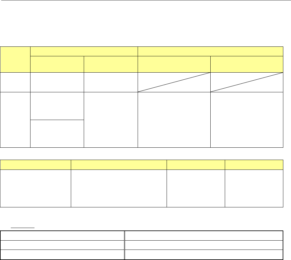
5.2.9. High resolution camera (Factory-Set Option)
When a line unit that permits switching between reflection and transmission recognition and
switching among wavelengths (red, blue, and green) is combined, fine-pitch components
(leads and balls) that cannot be recognized by standard camera can be recognized.
D
imensions of applicable components
(Unit: mm)
VCS batch recognition VCS Divided-image recognition
Reflection
lighting
Pass-through
lighting
Reflection lighting Pass-through lighting
MNVC
Min:1.0×0.5
Max:□20.0
Min:□3.0
Max:□6.0
IC head
KE-3020V
Min:□3.0
Max:□24.0
Min:□3.0
Max:□24.0
Maximum:
50×150(1x3 division)
or □74(2x2 division)
Maximum:
24×72 (1x3 division)
or □48(2x2 division)
KE-3020VR
Min:1.0×0.5
Max:□24.0
* Even though the dimensions exceed □ 20 mm, 24 mm×11 mm is acceptable.
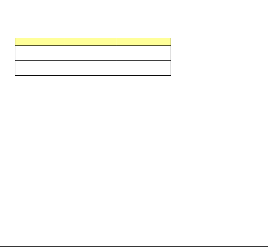
Lead pitch Component height Ball pitch Ball diameter
0.2~2.54
SC specification 0.08~6.0
NC specification 0.08~12.0
HC specification 0.08~20.0
EC specification 0.08~25.0
0.25~2.0 φ0.10~φ0.63
Lighting
Lead components reflection lighting Coaxial, downward and sideward lighting via red LEDs
Area array components sideward lighting Ball sideward lighting via blue LEDs
Pass-through lighting Profile pass-through lighting via green LEDs
* The quantity of light for lighting can be set for each component.
- 33 -
5.2.10. Applicability to long PWB (factory-set option)
The PWB size in the X direction can be extended by PWB twice-feed transport. This
permits producing long PWBs to be used for LED lighting. With the PWB exceeding the
single-feed size of the maximum size in the X direction shown in the following table,
twice-feed transport is performed.
Single-feed
Twice-feed
M PWB
330×250mm
650x250mm
L PWB
410×360mm
800×360mm
L-Wide PWB
510×360mm
1010×360mm
XL PWB
610×560mm
1210×560mm
Re
strictions
- The IN buffer/OUT buffer function is disabled.
- When MTC is used, a limitation is put on the maximum PWB size in the X direction that
can be transported.
5.2.11. Solder recognition lighting (factory-set option)
When there is no BOC mark on a PWB or circuit, the solder print is recognized as a BOC
mark. When executing twice-feed transport of long PWBs, the placement pad for which
solder print is performed can be used as a BOC mark in placement in a range without any
BOC mark.
*
I
n the case of the solder print, the shape is not clear as a mark, so that satisfactory
placement accuracy may not be obtained.
5.2.12. Residual number-of-components control function (option)
This function controls product lots of placement components (LED components, etc.). The
function checks whether the necessary number of placement components exists in the
feeder in carrying in PWBs without mixing different-lot components into the same PWB. If
the number is less than the necessary number, an alarm is displayed before placement is
started.
5.2.13. Auto PWB width adjusting function (Automatic Board Adjustment/AWC
factory-set option)
This function can adjust the rail width automatically according to the PWB width.
The minimum value of applicable PWB dimensions is 50mm x 50 mm.