KE-3010_SPE_EN - 第42页
- 37 - 5.2.18. Ionizer ( Factor y - Set Opti on ) This option maintains the ion balance inside the m achine to eliminate sta tic electricity and prevent it from b eing generated. This option prevents components as w ell …
- 36 -
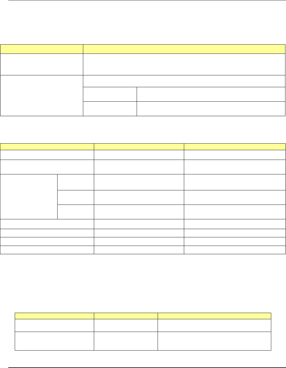
5.2.16. Fluxer (Factory-Set Option)
This is a flux supply device that applies flux to ball components such as a BGA, CSP and flip
chip (does not apply any adhesive or solder paste).
Y
ou can install this device on the mounter with either of the following two methods.
<
Where to install>
Installation position Remarks
Type 2
(To be attached on the main
unit)
Since this type of fluxer is attached on the base frame, any MTC cannot be attached
on the machine when the fluxer is attached. The number of component supply
devices to be attached on the bank is not restricted.
Type 3
(To be attached on a bank/Rear
side only)
The area for six mechanical 8-mm tape feeders (12 slots) is to be occupied.
Mechanical bank
The area for six mechanical 8-mm tape feeders (12 slots) is
to be occupied. (A connector bracket is required.)
Electric bank
The area for six electric 8-
mm tape feeders (6 slots) is to be
occupied.
Note 1: Either a fluxer or a rotary-type solder transfer unit option can be installed on the machine.
Note 2: The type of attached on an electric bank does not correspond to the Feeder exchange trolley RF.
<
Facility specifications>
Item
Specifications
Remarks
Applicable flux viscosity
8.4 Pa·s to 22.0 Pa·s
Cycle time required for flux application
and component placement
1,100cph
When the distance each of the X and Y
axes travels is 450 mm or less
Cavity dimensions
(*See Note 3.)
Depth
Minimum 0.02 mm (± 5 μm)
Maximum 0.2 mm (± 10 %)
Size
Maximum 30 mm×30 mm
(*See Note1 and 2.)
Maximum size of a cavity when only
one cavity is provided
Number of
cavities
1 to 4
Maximum eight on the top and bottom
sides
Power consumption
DC24V/0.3A
Life
5 years
(22 hours×300 days)/1 year
Parts needing periodic replacements
Electromagnetic valve, cylinder
Time for replacement: 2 years after use
Consumables
Fluxer plate, flux container
Time for replacement: 1 year after use
N
ote 1: The cavity size shall be “the maximum size of a component to be used” + “3-mm
margin around the component.”
Note 2: When two or more cavities are used, all cavities shall fit in the 30 mm×30 mm
area.
Note 3: If you need a cavity whose dimensions are not any of the JUKI standard
dimensions, contact our Sales person.
Standard part
Part number
Dimensions of a cavity
Fluxer plate 120/200 40044090
Size: X = 30 mm, Y = 30 mm
Depth: Front 0.12 mm/Rear 0.20 mm
Fluxer plate 30/50/70/100 40044091
Size: X = 30 mm, Y = 14 mm
Depth: Front A 0.03 mm/Front B 0.05 mm
Rear A 0.10 mm/Rear B 0.07 mm
5.2.17. Electrical Leakage Breaker (Factory-Set Option)
A standard breaker functions if any excess current flows or if a short-circuit fault occurs.
When you replace it with an electrical leakage breaker, this new breaker interrupts electrical
leakage, and then prevents the resulting electrical shock, so you can handle the machine
more safely.

- 37 -
5.2.18. Ionizer (Factory-Set Option)
This option maintains the ion balance inside the machine to eliminate static electricity and
prevent it from being generated.
This option prevents components as well as pick-up/placement operation of a component
from being damaged by static electricity to allow the machine to produce PWBs more stably.
5.2.19. IC Collection Belt (Option)
* The equipment is different between the mechanical bank and the electric bank. Use the
equipment suitable for each bank type.
- Applicable component size: 10 x 10 mm to 50 x 50 mm, Height: 1 mm or higher
- Belt feeding pitch: 15 mm to 55 mm (in increments of 5 mm)
- Number of components that can be collected: 5 to 16
- Number of occupied positions: 9
5.2.20. Handheld Operating Device (HOD: Factory-set option)
The KE-3010/3020V/3020VR allows you to check the recognized mark image on the
operation screen or perform various teaching operations. In addition, if an experienced
user of any of conventional mounters does not want to change the operability of the mounter,
or if you want to make the operability of the entire line consistent, you can use the HOD as
conventionally.
5.2.21. Tape Cutter Unit (Option for the electric type of bank)
This tape cutter automatically cuts empty tapes to dispose of them in a lump.
It is an integrated type of unit that is attached onto a main unit, and can be used with a fixed
bank and also an feeder trolley.
5.2.22. Automatic Tape Cutter (Option)
This tape cutter automatically cuts empty tapes to dispose of them in a lump.
5.2.23. Connector Bracket (Option for the Fixed Bank)
This is a unit necessary for connecting devices such as an adhesive tape feeder, an IC
collection belt, an automatic tape cutter and a DTS to the mounter. When the optional batch
feeder change function is selected, you do not require this unit.
5.2.24. Flexible Calibration System, The adjustment jig (FCS is an option.)
After a jig component that is recognized with the VCS or laser is placed on a glass jig board,
the FCS uses a camera to automatically measure the difference between a value set with the
program and the position at which the component is placed, and calculates the offset value
to be used for placing the component.
A series of operations can be automatically performed by setting the jig PWB and reading the
program.
When you use the FCS, you can check whether the precision is maintained and adjust the
precision at relocation or routine maintenance.
The calibration jig is optional.

- 38 -
5.2.25. Placement Monitor (Factory-Set Option)
This system uses an ultra-miniature camera attached on the mounter head to take two
pictures before and after a component is picked up during PWB production, and take three
pictures before, while and after a component is placed on a board. It, then, sends these
pictures to the computer for the placement monitor system. You can check these pictures
to analyze the cause of an error.
By comparing two pictures taken before and after a component is placed on a board, you can
check to see if a component exists or not also.
Features
(1) Function for shooting images of component pick-up/placement
• The micro miniature camera takes pictures when a component is picked up and w
hen
i
t is placed on a board.
• An image can be shot for each nozzle.
• You can specify whether to shoot an image or not with a production program.
• An obtained image can be displayed onto a computer for the Placement Monitor in real
time.
• I
f a communication error occurs, the corresponding error is displayed on the Mounter.
• User’s visual check can obtain an optimum parameter, or shorten the time for
analyzing the cause of a trouble.
(2) Trouble cause analyzing tool
• Recorded images are linked to the mounter and the computer for the Placement
Monitor, and a database of these images is made.
If any trouble occurs, search through the database allows you to analyze its cause
easily.
(3) Setup Assistance
• When the current lot is switched to a new one, the optimum pick-up/placement
parameters can be verified.
• An image of a component normally placed on a board can be stored onto the database
as the master image, and this image and an image of placement operation bei
ng
per
formed during PWB production can be displayed side-by-side.
(4) Movie mode
• Two or more images of a component pick-up operation can be shot, and th
en
di
splayed continuously with a computer for the Placement Monitor.
• You can select the movie mode: “mode for increasing the number of images that c
an
be s
hot by setting the Z-axis speed to ‘Low’” or “mode for repeating picking up two or
more components and rearranging the shot images by setting the Z-axis speed to
optional”
(5) Judgment of existence of a component
• The function of the Placement Monitor System that automatically judges if
a
c
omponent exists or not prevents a component placement trouble.
• You do not have to enter any parameter for judging existence of a component.
Applicable component sizes:
Minimum size
0.4
×
0.2 (mm)
Maximum size
5.0
×
5.0 (mm)
Height
2.0 (mm)
Packaging (feeder) type
Tape feeder, Tray holder ,DTS
(6) Digital-zooming function
• A stored image can be zoomed.
• Components from a minute one, 0402 (mm) component are supported, and a shot
image of such a small component is enlarged by default.