KE-3010_SPE_EN - 第45页
- 40 - Exclusive Computer for the P lacement Monitor system One computer with the f ollowing specifications is required for one moun t e r. The computer is to be us ed exclusively for the Placement M onitor system. S pec…
- 39 -
(7) Database management
• Its simple search function can shorten the time for searching data.
• You can conduct database search with various queries.
(8) Bar-code recognition function of the PWB
(Barcode, 2-D code)
• By using the function for recognizing a barcode and/or 2-D code on a board, you can
set the PWB code in the database of the taken pictures.
Note: Prepare a barcode reader assembly (for a barcode and a 2-D code) separately.
When you use this system with the IFS-NX/IntelliPD, you do not have to prepare this
assembly.
Barcode reader assembly
Barcode: Barcode on the topside of a board is read at the upper section of the
board carry-in entrance.
2-D code: 2-D code on the topside of a board is read with an OCC attached on the
head.
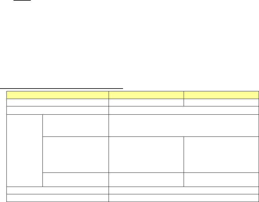
Specifications of the Placement monitor
KE-3010
KE-3020/20VR
View field
12X7.5mm
10.3X7.3mm
Focus depth
(
PWB Top View
)
±2mm
Captured
images
Per image
approximately 200 KB (**.bmp) approximately 50
~
120 KB (**.png)
(Monochrome)
Per hour
Approximately 18.5GB
(Approximately 200KB ×
5 images × 15,400CPH)
(Conforming to the
IPC9850.)
Approximately 17.1GB
(Approximately 200KB ×
5 images×17,100 CPH)
(Conforming to the
IPC9850.)
Per 1TB of hard disk
Approximately 55 hours
(18,500 CPH)
Approximately 59 hours
(17,100 CPH)
Supported languages *
English and Japanese
Destination
Europe, Japan, China and Southeast Asia
* The cycle time will take longer by up to 3% when the placement monitor is used. In addition,
when the setting “The system pauses if a component existence error occurs” is enabled, the
cycle time will take longer by up to 30%.
* When the supported language of the machine main unit is Chinese, the application of the
placement monitor is written in English.
- 40 -
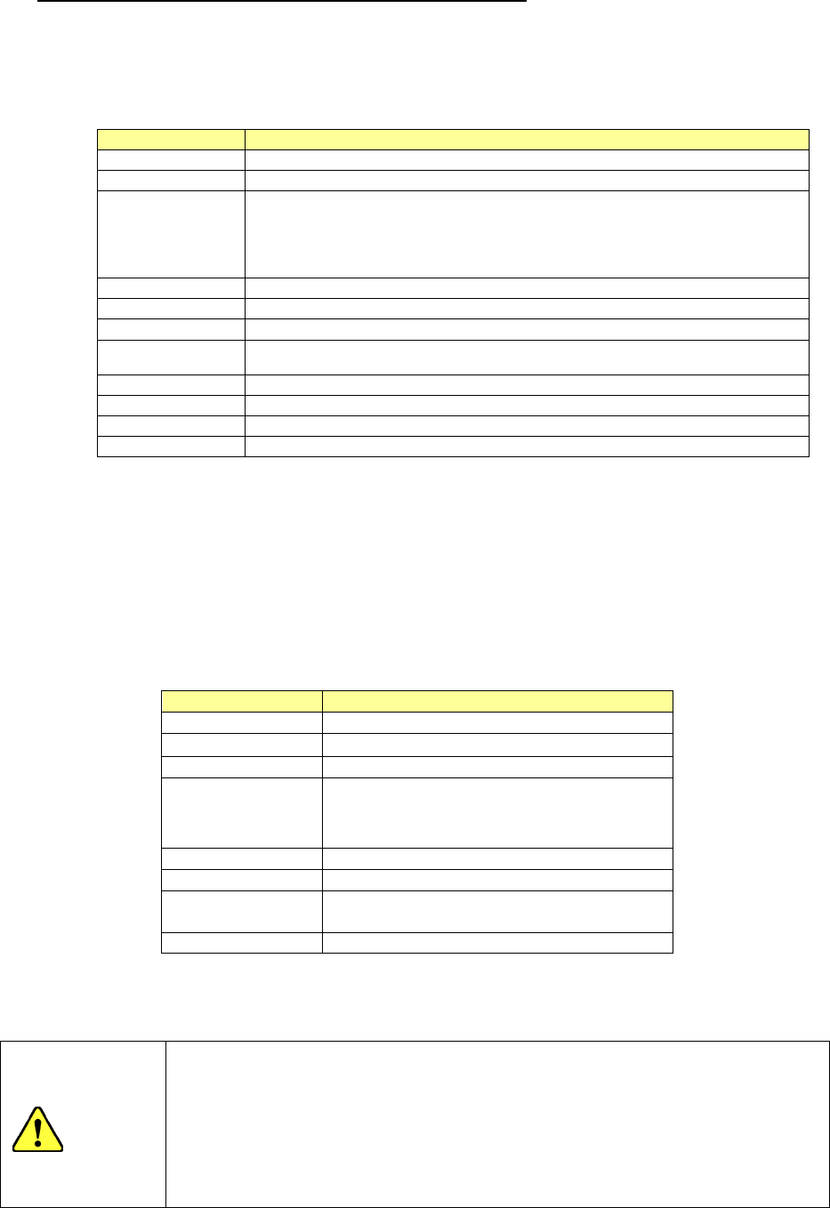
Exclusive Computer for the Placement Monitor system
One computer with the following specifications is required for one mounter.
The computer is to be used exclusively for the Placement Monitor system.
S
pecifications of the computer for Placement Monitor
Recommended specification
CPU
2.66 GHz or higher (Intel Core™ Quad or higher)
Memory
4 GB or more
HDD capacity
C drive
:
750 GB or more (SATA)
D drive:2.25 TB or more (SATA ,RAID 0)
(Create C drive and D drive; create the data storage area in D drive.)
Note 1 and 2
Chipset
Intel X58 chipset or, or the equivalent
DVD-ROM drive
One
USB port
1 port or more
Monitor
resolution
1024 × 768 or higher
Expansion slot
PCI bus, full-sized 1 slot*
OS
Microsoft Windows 7 Professional 32bit (The OS shall be clean-installed.)
Software
Any software other than designated one must not be installed.
Recovery media
OS recovery disk
*1 External hard Drive D cannot execute the system.)
*2 Y
ou have to add an IEEE1394a expansion card designated by JUKI to communicate with
a Mounter.
*3 HDD capacity of the recommended specifications is approximately 1.3 M images
(**.bmp) (equivalent to 2.6 M components).
T
he reference model should be DELL Precision T3500 Mini Tower Mode Package, or the
equivalent. If you cannot purchase the reference model, refer to the recommended
computer specifications and select one.
Reference model
Model
Dell Precision T3500 Mini Tower Mode
CPU
Intel Xeon™ W3530
(
2.80 GHz
)
Memory
4 GB
HDD capacity
C drive
:
1TB (SATA)
D drive:1.5TB×2 (SATA ,RAID 0)
(
※
RAID will be set up after purchase)
Chipset
Intel X58 chipset
DVD-ROM drive
One
OS
Microsoft Windows 7 Professional 32bit
(The OS shall be clean-installed.)
Recovery media
OS recovery disk
* Intel, Core and Xeon are trademarks of Intel Corporation in the U.S.A. and other countries.
* Dell and Dell Precision are trademarks of Dell Inc. in the U.S.A. and other countries.
Precautions for preparing a computer for the Placement Monitor
system
Do not install any software other than the applications of Placement Monitor
to avoid communication failures. If other software (such as a writing
software, DVD player, printer support software or others that run in the
background) exists, a clean install of the OS is required.
CAUTION
- 41 -
5.2.26. Rotary-type Solder Device (Factory-Set Option)
This device transfers solder onto a ball-terminal component such as a BGA, a CSP and a flip
chip.
You can adjust the thickness of solder to be transferred with the squeegee installed on the
solder tray.
R
ecommended solder paste
M705-TVA Series (Senju Metal Industry Co., Ltd.) (Viscosity: 30 Pa·s)
A
pplicable components
Component dimensions: 14 mm×14 mm or less
Ball diameter: 0.36 mm or more
Ball pitch: 0.5 mm or more
S
older application specifications
Thickness of solder: 40 μm or more
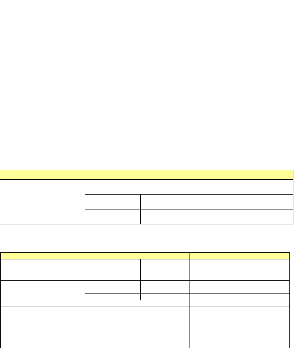
<
Where to install>
Installation position Remarks
To be attached on a bank
(Front side only)
To attach the device on a bank, see the figures desc
ribed below for the number of
component supply devices that can be installed on the machine.
Mechanical bank
The area for six mechanical 8-mm tape feeders (12 slots) is
to be occupied. (A connector bracket is required.)
Electric bank
The area for six electric 8-
mm tape feeders (6 slots) is to be
occupied.
Note1: Either a fluxer or a rotary-type solder transfer unit option can be installed on the machine.
Note2: It does not correspond to the Feeder exchange trolley RF.
<Facility specifications>
Item
Specifications
Remarks
Type
For a mechanical
bank
SWR1MB
For an electric bank SWR1EB
Total weight
For a mechanical
bank
3.2kg
For an electric bank
4.4kg
Transfer position
One position
Cycle time obtained when a
solder is transferred and a
component is placed on a board
1180cph
Power consumption 1.5 W (100 V AC/15 mA)
Parts to be replaced on a regular
basis
Squeegee
To be replaced when it is chipped,
worn out or deformed.