KE-3010_SPE_EN - 第65页
- 60 - SOJ ( EI AJ E D - 740 6 ) St ack Stick Feeder t yp e Lane wi dt h ( mm ) Groove depth ( mm ) Nominal component size Component w i dt h ( mm ) Component height ( mm ) Componen t length ( mm ) Distance from the bo…
- 59 -
・
Feeder type: Type W (SFW*EB)
Model
Lane width
[mm]
SOP
SOJ
PLCC(QFJ)
Nominal
size
[mil]
Element
width
[mm]
Element
height
[mm]
Nominal
size
[mil]
Element
width
[mm]
Element
height
[mm]
Nominal
size
[mil]
Element
width
[mm]
Element
height
[mm]
SFW1EB
(Type W1)
15.0 525
13.34~
14.61
3.5
SFW2EB
(Type W2)
18.2
600
15.24~
16.51
4.0
650
17.40~
17.65
4.20~
5.08
SFW3EB
(Type W3)
20.8
750
19.94~
20.19
SFW4EB
(Type W4)
26.0
950
25.02~
25.27
SFW5EB
(Type W5)
31.2
1150
30.1~
30.55
- For Types N1 to N4 and types W1 to W5, an optional spacer kit is available for a change to another type.
- Type N0 is dedicated for SOP8 and 10 pins and permits adjusting the clearance with the attached spacer to
obtain the optimum lane width.
Use a dedicated stick feeder matched to each element size. Otherwise,
elements may be broken due to inaccurate operation even if they are
caused to flow.
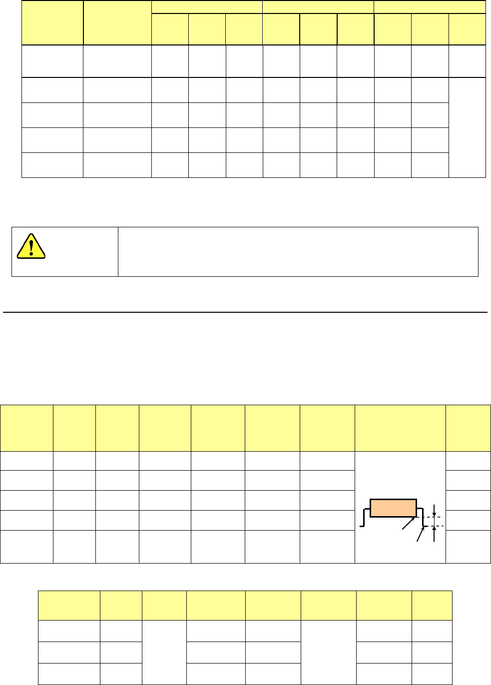
6.5. Stack Stick Feeder (for a mechanical bank)
A stack stick feeder is to be installed on the fixed bank, which is a section of a JUKI mounter
on which a feeder is to be installed, or a feeder exchange trolley, and feeds sticks of
components such as SOP, PLCC and SOJ with stacked on one another to the pick-up position
of the mounter automatically.
SOP
(
EIAJ ED-7402-1
)
Stack Stick
Feeder
type
Lane
width
( mm )
Groove
depth
( mm )
Nominal
component
size
Component
width
( mm )
Component
height
( mm )
Component
length
(
mm
)
Distance from the
bottom of a lead to
that of a mold (“A”)
(mm)
See Note 1.
Stick
width
(
mm
)
Type 1 7.0 1.7
TYPE I
225 mil
5.72 to
6.99
1.01 to
1.50
8.89 to
13.97
0.4 or less
<Note 1:
Distance “A”>
8 to 10
Type 2 9.0 2.3
TYPE
Ⅱ
300 mil
7.62 to
8.89
1.51 to
2.00
11.43 to
13.97
10 to 12
Type 3 10.8 2.8
TYPE
Ⅲ
375 mil
9.53 to
10.80
2.01 to
2.50
11.43 to
16.51
12 to 14
Type 4 12.8 3.3
TYPE
Ⅳ
450 mil
11.43 to
12.70
1.80 to
3.00
13.97 to
19.05
14 to 16
Type 5 14.8 3.8
TYPE Ⅴ
525 mil
13.34 to
14.61
3.01 to
3.50
13.97 to
24.13
16 to 18
QFJ
(
PLCC
)(
EIAJ ED-7407
)
Stack Stick
Feeder type
Lane
width
( mm )
Groove
depth
( mm )
Nominal
component
size
Component
width
( mm )
Component
height
( mm )
Component
length
(mm)
Stick
width
(mm)
Type 3L 10.8
5.1
TYPE I
350 mil
9.78 to
10.03
4.20
to
4.57
9.78 to
15.11
12 to 14
Type 4L 12.8
TYPE Ⅱ
450 mil
12.32 to
12.57
12.32 to
15.11
14 to 16
Type 6L 18.0
TYPE Ⅲ
650 mil
17.40 to
17.65
17.40 to
17.65
18 to 20
Bottom
A
CAUTION
- 60 -
SOJ
(
EIAJ ED-7406
)
Stack Stick
Feeder
type
Lane
width
( mm )
Groove
depth
( mm )
Nominal
component
size
Component
width
( mm )
Component
height
( mm )
Component
length
(
mm
)
Distance from the
bottom of a lead to
that of a mold (“A”)
(mm)
See Note 1.
Stick
width
(
mm
)
Type 2J 9.0
4.0
TYPE I
300 mil
8.382 to
8.763
3.251
to
3.759
10.922 to
21.41
1.2 or less
10 to 12
Type 3J 10.8
TYPE
Ⅱ
350 mil
9.652 to
10.033
13.462 to
29.00
12 to 14
Type 4J 12.8
TYPE
Ⅲ
400 mil
10.922 to
11.303
17.272 to
29.00
14 to 16
TYPE Ⅳ
450 mil
12.192 to
12.573
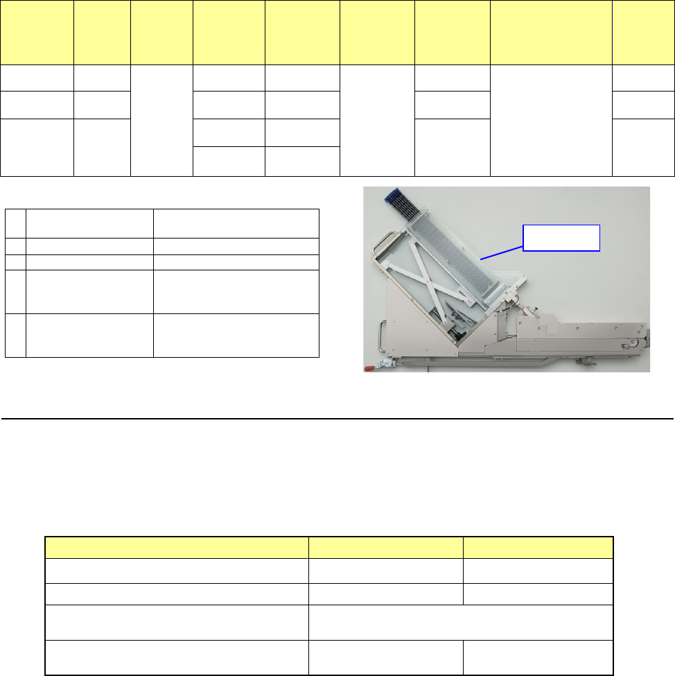
•
Stack Stick Feeder Specifications
1
Number of the
occupied positions
8
2
Supply voltage
DC24V
、
DC6V
3
External dimensions
8.5kg
4
Weight
Width =60mm
Height =580mm
Length =930mm
5
Dimensions of an
applicable stick
Width =20 mm or less
Height =10 mm or less
Length =400 to 600mm
6.6. Tray Holder
*Choose an appropriate device for the mechanical or the electric type of bank.
This tray holder is equipped with one tray, and can be installed on the rear bank so that the
head of the main unit can pick up a component directly from this holder.
When the tray size is small, several trays can be attached on the holder to allow this holder to
function as a multi-tray holder.
Full type Half type
Longitudinal direction 65 mm to 320 mm 65 mm to 155 mm
Horizontal direction 65 mm to 259.5 mm 65 mm to 259.5 mm
Thickness
5 mm to 11 mm
(from the bottom of a tray to the top of an IC)
Number of occupied positions
Mechanical: 42
Electric: 20
Mechanical: 21
Electric: 10
* A number of available places at the rear side.
- Full type: 2 tray holders, - Half type: 4 tray holders
*
The number of feeder positions actually occupied by outline is 40 for the full type or 20 for the
hal
f type. However, the number of positions used at production (on the feeder layout) is as
shown in the above table.
Magazine

- 61 -
6.7. TR Series
TR series device supplies a mounter with a tray component.
The three types of DTS (Dual Tray Server), MTS (Matrix Tray Server), and MTC (Matrix Tray
Changer) are available. For MTS and MTC, the standard type and non-stop type are
available. In the case of the non-stop type, two tray stackers are used for independent shaft
control and components can be changed without stopping production even if “no components”
occur. (In DTS, the standard mode or non-stop mode can be selected by software.)
*1 TR**R series models that have been used with conventional mounters are not supported.
Regarding the correspondence table for the TR**X series and TR**V series, check “6.7.2
Correspondence table for the TR series.”
*2 TR6DXLX/6SXLX models are to be used exclusively for a mounter designed for an
XL-sized board.
*3: For the wide PWB specification, and fluxer type 2 specification, MTC cannot be installed.
*4: For the fluxer type 3 specification, MTS cannot be installed.
6.7.1. Overview
(1) TR1SNR/TR1EB (DTS, Dual Tray Server)
This is a tray supply device on which two trays can be set, and is to be installed on
feeder bank of the rear bank so that the head of the mounter can pick up components
directly from this tray server. If this device is used in the non-stop mode where a tray
change of the same components is performed alternately, the tray change can be
performed without stopping the main unit at occurrence of “no components.”
Since the head of the mounter directly picks up components from this tray server, even
irregularly-shaped components can be supplied easily.
(2) TR5SNX (MTS, Matrix Tray Server) /TR5DNX (MTS, matrix tray server, non-stop type)
This matrix tray server is to be installed on the rear bank of a mounter, and pulls out all
trays at a time so that the head of the mounter can pick up components directly from the
trays. Since the head of the mounter directly picks up components, even
irregularly-shaped components can be supplied easily.
(3) TR7DN (MTS, high-speed matrix tray server, non-stop type)
This device is installed in the rear bank. With a two sets of tray tracker (hereinafter
called stacker), components are transported and supplied alternately on the same plane
from the tray stacker to the pickup position. When same components are set in both
stackers, they can be supplied automatically without stopping the main unit from the
other stacker even if one stacker becomes empty.
(4) TR6SNV, 6SXLX (MTC, matrix tray changer)/TR6DNV, 5DXLX (MTC, matrix tray
changer, non-stop type)
This is a tray changer equipped with a shuttle type conveyor that supplies various types
of tray components.
This can supply a mounter with tray components without reducing the number of tape
feeders provided.
Note: When Barcode is used for the traceability, MTC (TR6SNV/6DNV) cannot be used
with a mounter, of which transport direction is “Right to Left”.