KE-3010_SPE_EN - 第72页
- 67 - 6.8.3. Facility Sp ecifica tion Item Content s Power supply V oltage Single - pha se AC 200V/220V /240v ( ± 10%) Frequency 50 / 60 Hz A ppare nt power 1.5 k VA Compress ed air to be used Air pressure 0.5 ± 0.05 M …
- 66 -
6.8. Multi-die server
6.8.1. Overview
This equipment DF01 (multi-die server, hereafter referred to as “this equipment”) is designed
to supply bare chips from the wafer or waffle tray to the mounter in a process where
components, such as Sip (System In Package) and MCM (Multi Chip Module) and devices
advancing more compact sizes are mixed. Face-up or face-down (flip) supply and
high-speed simultaneous pickup can be selected. This makes the equipment applicable to a
wide variety of applications.
* Refer to the “DF01 PRODUCT SPECIFICATIONS” for details.
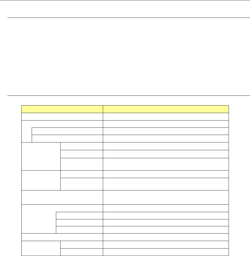
6.8.2. Basic Specifications
Model
DF01
Applicable language
Japanese, English
Supply style Wafer/waffle tray
Wafer supply
Grip ring (for 4-, 5-, 6-, or 8-inch)
Tray supply Waffle tray (2- or 4-inch)
Component
size
Direct supply
0.3 mm to 10.0 mm Note 1
Shuttle supply 1.0 mm to 10 mm
Allowable
thickness
0.05 mm to 0.725 mm
Target
component to
be used
Wafer Bare chip
Package
component
BGA or CSP, etc. (up to 10 mm)
Supply method
• Face-up supply by shuttle
•
Face-down supply by shuttle (flip chip)
Number of storage pallets
10 pcs.
Grip ring
1 pc./pallet
2-inch waffle tray
8 pcs./pallet (option)
4-inch waffle tray
4 pcs./pallet (option)
Component supply speed 2,400 CPH
Supply
accuracy
XY
±
0.1 mm
θ
±
5
°
Note 1: Separate measures are taken for a size ranging from 10.0 mm to 25.0 mm. For details,
contact JUKI’s sales personnel.
- 67 -
6.8.3. Facility Specification
Item Contents
Power supply
Voltage
Single-phase AC 200V/220V/240v (
±
10%)
Frequency 50/60 Hz
Apparent power 1.5 kVA
Compressed air
to be used
Air pressure
0.5
±
0.05 MPa, dry air
Max. air consumption
150 L/min. (standard status) ∗
Note 1
Noise
75 dB (A) or less
∗
Note 2
Degree of cleanliness Class 10,000 or less
Note 1: Standard status: Air status with a temperature of 20
°
C, an absolute pressure of
0.1 MPa (= 100 kPa =1 bar), and a relative humidity of 65%
Note 2: Noise is measured in conformity with JIS Z 8731.
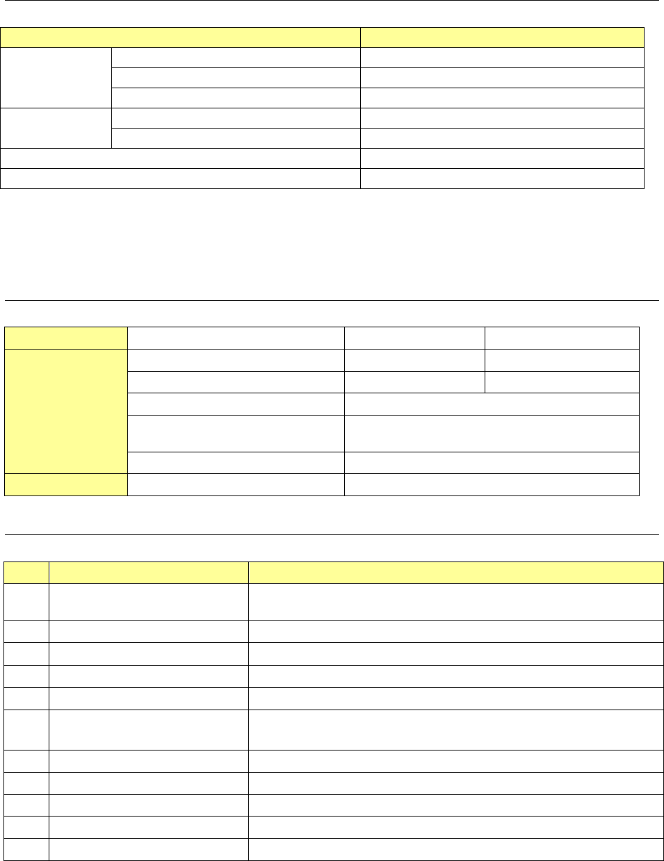
6.8.4. External dimensions
Item
Board transport height 900mm 950mm
Dimensions
Height H (with signal light) 1,955 2,005
Height H (without signal light) 1,400 1,450
Width W 696
Depth D
(from mechanism part to handle)
1,160
Dimensions with cover open 450
Weight
Approx. 340kg
6.8.5. Options
No. Name Description
1
Heater (Option to be attached
at shipment from the factory)
Heater for the push-up unit
2 Pallet for a grip ring Pallets for 4-, 5-, 6-, and 8-inch wafers are available.
3 Grip ring
Grip rings for 4-, 5-, 6-, and 8-inch wafers are available. See n
ote 1
4 Pallet for a waffle tray Pallets for 2- and 4-inch waffle trays are available.
5 Needle For push-up of a bare chip
6 Collet For absorption of a bare chip
A collet for each size of bare chip is available.
7 Stacker Additional stacker (not including a pallet)
8 Pallet for a 6-inch flat ring Pallet on which a wafer is to be attached directly
9 Grip ring replacement jig Jig for attaching a wafer on a grip ring
10 Wafer alignment jig Jig for attaching a wafer parallel to a pallet
11 Leveling jig pallet Pallet for leveling the machine
Note 1: When you purchase an option from the recommended manufacturer:
ULTRONICS INC. http://www.ultronics.co.jp/
Manufacture’s model name 4-inch: GRP-2620-44 5-inch: GRP-2620-5
6-inch: UGR-6 8-inch: UGR-8

- 68 -
7.
Control System
7.1. Control
7.1.1. Saving a program
KE-3010/3020V/3020VR mounter store a production program onto the SSD in the main unit.
When you use a USB port, you can store it on an external storage device also.
7.1.2. Limit of a production program
● Maximum number of placement points per circuit : 10,000 points
● Maximum number of circuits per PWB : 1,200 for a matrix board
200 for a non-matrix board
● Maximum number of points per PWB : 10,000 points
● Maximum number of component data records : maximum number of component
types that can be attached on the machine
● Maximum number of component pick-up records : same as the above.
● Maximum number of Area Fiducial marks :
50 sets for component placement positioning mark,
1 set for a BOC mark (2 to 3 marks)
7.2. Production Mode
The following three production modes are available during production:
PWB production
- Specifies the number of PWBs you plan to produce and produces PWBs actually.
Trial mode
- Performs a trial PWB production.
You can select the PWB pick-up position tracking function or PWB placement position
tracking function that is to be performed after placement.
Dry run mode
- Checks the PWB pick-up/placement process without using any component.
You can select the PWB pick-up/placement position tracking function.