KE-3010_SPE_EN - 第75页
- 70 - 8.2.1. Specificati ons of the connecting cable Complied with JIS B 8438 Industrial Robo ts - Electrical Equipment Cable length: 10m or less 8.3. Data interface LAN port ( 10/100 Base -T ) 8.4. Utilit y connecti on…
- 69 -
8.
Other Specifications
8.1. Electrical interfaces
8.1.1. Kinds and meanings of electrical signals
The conceptual diagram of the electrical signals both on the mounters and the other side
machines is shown, as follows: The electrical signals between the mounters and
upstream-side devices ①, ② and between the mounters and downstream-side devices ③,
④ is shown in the following diagram.
a) The electrical signal ① is called the “transport request input signal (or PWBs
available-in),” receiving the PWBs transport requests from the upstream-side devices.
b) The electrical signal ② is called the “transport permit output signal (or ready-out),”
having the PWBs carried out to the upstream-side devices.
c) The electrical signal ③ is call the “transport request output signal (or PWBs
available-out),” requesting the PWBs transport to the downstream-side devices.
d) The electrical signal ④ is called the “transport permit input signal (or ready-in),
“ receiving the PWBs transport permits from the downstream-side devices.
Figure
Conceptual diagram connecting the electrical signal
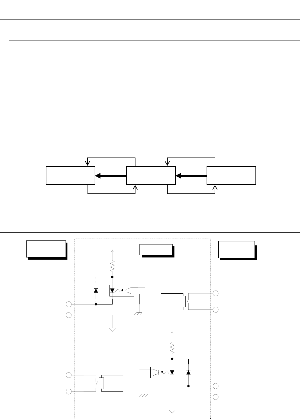
8.2. Specifications for connections between the front and rear devices
Figure
Signal interfaces and connection terminals
Downstream-
side devices
Mounters
Upstream-
side devices
④
③
②
①
Pin No. 1 :
Transport permit input signal
Pin No. 2 :
Transport permit common
signal
Relay contact
Downstream-
side devices
Mounter
Upstream-
side devices
Pin No. 3 :
Transport request output signal
Pin No. 4 :
Transport request common
signal
Pin No. 1 :
Transport permit output signal
Pin No. 2 :
Transport permit common signal
Pin No. 3 :
Transport request input signal
Pin No. 4 :
Transport request common signal
Relay contact
+24V
+24V

- 70 -
8.2.1. Specifications of the connecting cable
Complied with JIS B 8438 Industrial Robots - Electrical Equipment
Cable length: 10m or less
8.3. Data interface
LAN port (10/100 Base-T)
8.4. Utility connections
Piping joint
One-touch connecting plug for theφ8×φ12 hose

- 71 -
9.
Safety specifications
9.1. Standards specifications
Emergency stop
The machine is provided with the two (2) emergency stop buttons each at the front and rear
sides. (The one (1) emergency stop button is provided when the optional HOD is attached on
the machine.) Depressing these emergency stop buttons immediately stops each axis to cut
off the power supply for driving the motors.
Safety covers
The machine is provided with covers, each at the front and rear sides, for both of which the
cover open switch detects either status of opening or closing to suspend the continuous
operation temporarily upon opening either cover or both. Moreover, the machine is
provided with the "Switching key" on the operation panel that switches "Maintenance
mode" or "Operation mode" to perform switching operation of safety covers according to
each mode.
・ Operation mode
It is a mode that enables a safety cover to be locked, and limits opening of cover during
normal production. Moreover, it releases the safety cover from being locked in operation,
and frees the servomotor "SERVO FREE state" for the safety operation while the safety
cover opens.
・ Maintenance mode
It is a mode that enables the low-speed operation while a safety cover is not locked and
opened, and is used for maintenance.
9.2. Specifications for the CE Marking (for EN Machine)
This shall comply with the following EC (European committee) instructions
− EC mechanical instructions: 2006/42/EC
− EC EMC instructions: 2004/108/EC
Applicable standard
・Machinery Directive EN ISO12100:2010, EN ISO13849-1:2008, EN 60204-1: 2006, others
・EMC Directive EN 61000-3-2: 2006, EN 61000-3-3: 1995/A1: 2001/A2: 2005,
EN 61000-3-11: 2001, EN 61000-6-4: 2007, EN 55016-1-2 : 2004,
EN 55016-2-1: 2004, EN 55016-2-3 : 2006, EN 61000-6-2: 2005,
EN 61000-4-2: 1995/A1: 1998/A2: 2001, EN 61000-4-3: 2006,
EN 61000-4-4: 2004, EN 61000-4-5: 2006, EN 61000-4-6: 2007,
EN 61000-4-8: 1998, EN 61000-4-11: 2004