00191297-02.pdf - 第166页
5 Single Functions User Manual SIPLACE S -23 HM 5.3 Single functions, Transport Software Version SR.405.xx 05/99 Issue 164 5.3.2.1 General comment s The "PCB c onveyor wi dth" screen m akes av ailable all fu nc…
User Manual SIPLACE S-23 HM 5 Single Functions
Software Version SR.405.xx 05/99 Issue 5.3 Single functions, Transport
163
5.3.2 "PCB conveyor width" screen
5
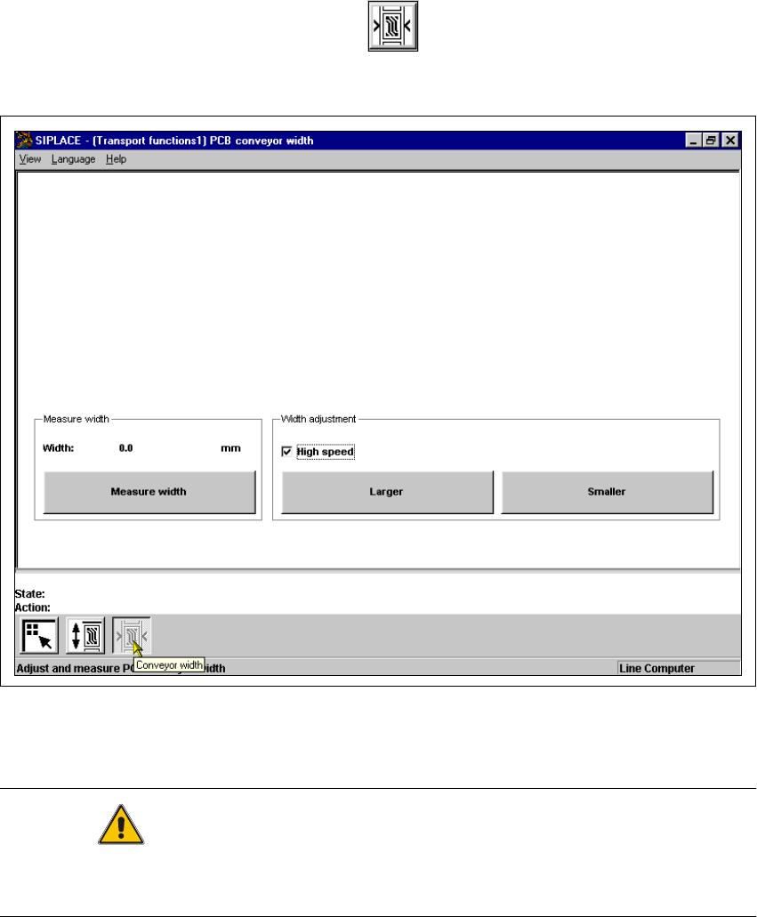
È In the "Transport functions" screen, click the symbol.
The user interface is switched to the "PCB conveyor width" screen (see Fig. 5.3 - 2).
5
Fig. 5.3 - 2 "PCB conveyor width" screen
5
CAUTION
Before adjusting the conveyor width, make sure there are no boards or other objects on the
machine’s conveyors. Failure to do so may result in damage to both machine and boards!
5
5 Single Functions User Manual SIPLACE S-23 HM
5.3 Single functions, Transport Software Version SR.405.xx 05/99 Issue
164
5.3.2.1 General comments
The "PCB conveyor width" screen makes available all functions necessary to adjust the width of
the conveyor.
It may be necessary to change the width of the conveyor, for example, for maintenance work or
when introducing a board with new dimensions. 5
The conveyor can be adjusted to suit the width of the board.
Incremental width adjustments are made by clicking the buttons "Larger" or "Smaller" (see section
5.3.2.2).
Width adjustments can be made in large increments (increment size = 1 mm) or in smaller steps (in-
crement size = 0,1 mm). This can be controlled by activating or deactivating the "High speed" check
box in the "Width adjustment" area (see section 5.3.2.2). 5
5
5.3.2.2 Functions
Measure width 5
This function can be used to measure the current width of the conveyor. The result is shown and
saved.
È Click the Measure width button.
The measured width is displayed above the button.
5
Incremental adjustment
È Activate the "High speed" check box to adjust the conveyor width in large increments.
Deactivate the check box if you want to adjust the conveyor width in smaller steps.
5
Conveyor width adjustment
Larger 5
È Click the Larger button to increase the width of the conveyor.
Each time you click the button the width is increased by the increment size set using the
"High speed" check box.
Smaller 5
È Click the Smaller button to reduce the width of the conveyor.
Each time you click the button the width is reduced by the increment size set using the
"High speed" check box.

User Manual S-23 HM 6 Vision functions
Software Version SR.405.xx 05/99 Issue 6.1 The vision systems on the placement system
165
6 Vision functions
6.1 The vision systems on the placement system
The quality requirements concerning the accuracy of automatic placement systems are constantly
rising, for several reasons: 6
– continuing miniaturization of components,
– increasing lead connection density,
– increasing complexity of PCBs and
– increasing component density.
To help meet these requirements, high-precision mechanical components are combined with op-
tical centering and detection systems (known as vision systems) for components and PCBs. 6
The placement system has two gantries (see Fig. 6.1 - 1). On each of these gantries there is a
DLM1 revolver head with a separate component camera system (see Fig. 6.1 - 2). A PCB camera
system is mounted on the underside of the head mount of each gantry (see Fig. 6.1 - 3). 6
Vision analysis units 6
The vision analysis unit plugs into the control unit (see items 1 and 2 in Fig. 6.1 - 4). The compo-
nent and PCB cameras, combined with the vision analysis unit form the vision system. 6
The electrical image signals from the component and PCB camera systems are sent to the vision
analysis unit (see items 1 and 2 in Fig. 6.1 - 4), where the measured values are compared with
the artificial values from the component description or PCB fiducials. The result is used to calcu-
late the correction factors for the individual placement positions. 6
The components are also identified by their package forms. The component is not placed if the
artificial model and the package form measurement do not correspond. 6
The PCB vision system can also be used to detect the position of the feeder modules. Fiducials
on the feeder modules are used to calculate the position deviation of individual feeder modules.
The pick-up reliability can be greatly increased in this way, even for tiny components. 6