00191297-02.pdf - 第169页
User Manual S-23 HM 6 Vision functions Software Version S R.405.xx 05/99 Issue 6.1 The vision systems on the placement system 167 6 Fig. 6.1 - 2 Com ponent camera sy stem Key to Fig. 6.1 - 2 (1) 12-nozzle rev olver head …
6 Vision functions User Manual S-23 HM
6.1 The vision systems on the placement system Software Version SR.405.xx 05/99 Issue
166
6
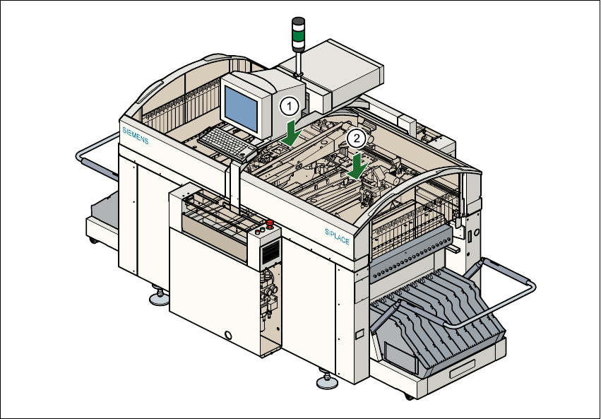
Fig. 6.1 - 1 Position of the gantries and DLM1 revolver heads
Key to Fig. 6.1 - 1
(1) Gantry 1 with DLM1 revolver head and component and PCB vision system
(2) Gantry 2 with DLM1 revolver head and component and PCB vision system
6.1.1 Component camera system on the revolver head
The component camera system (see item 2 in Fig. 6.1 - 2) essentially consists of the following
modules: 6
– Lens system
– CCD chip for creating an electronic image of the component
– CCD camera amplifier
– Three illumination planes - flat, medium and steep - for optimum lighting of a wide range of
component shapes
– "Illumination control" board for setting the intensity of the individual illumination planes
User Manual S-23 HM 6 Vision functions
Software Version SR.405.xx 05/99 Issue 6.1 The vision systems on the placement system
167
6
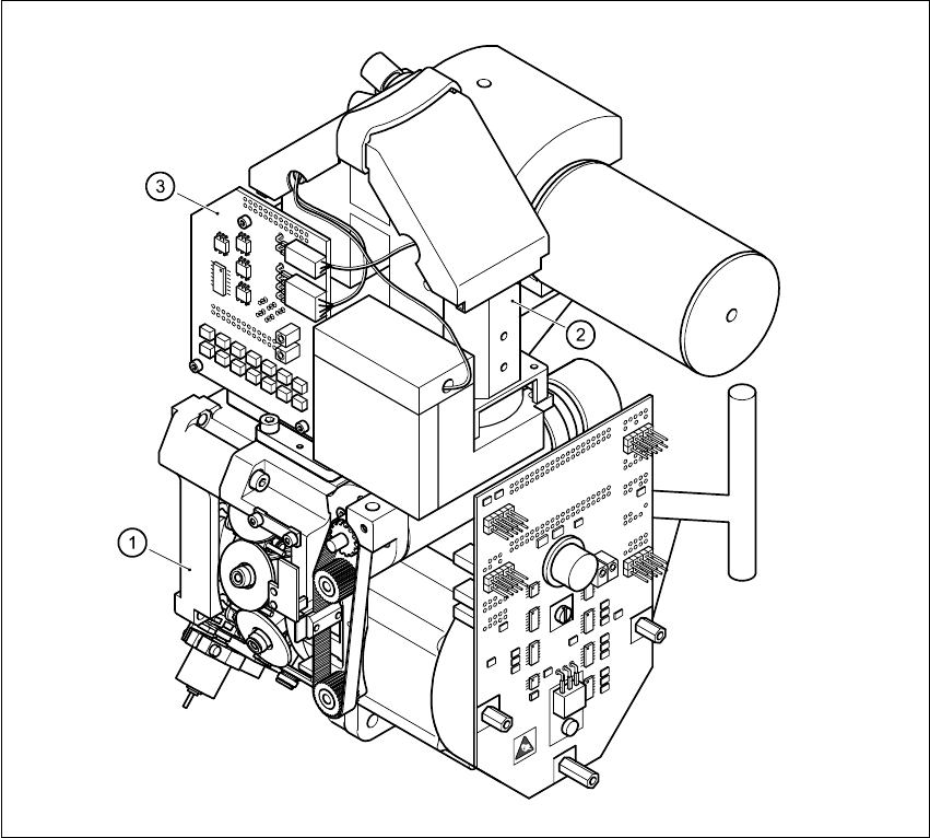
Fig. 6.1 - 2 Component camera system
Key to Fig. 6.1 - 2
(1) 12-nozzle revolver head /DLM1
(2) 24 x 24 component camera
(3) Component illumination control board
6
The component camera system is fastened to the top of the revolver head with four hexagon
socket-head screws and is fixed in position with two parallel pins. 6
The component camera system can be used to optically center and place components ranging
from 0402 up to and including SO32 in size. The components, therefore, can vary between
1.0 mm x 0.5 mm and 18.7 mm x 18.7 mm in size and from 0.3 mm to 6 mm thick. The minimum
lead pitch can be as little as 0.5 mm. 6
6 Vision functions User Manual S-23 HM
6.1 The vision systems on the placement system Software Version SR.405.xx 05/99 Issue
168
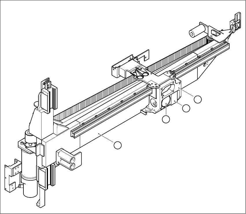
6.1.2 PCB camera systems
Fig. 6.1 - 3 PCB camera system, basic gantry - bottom view
Key to Fig. 6.1 - 3
(1) PCB camera - lens and illumination
(2) Camera amplifier
(3) Head mount
(4) Gantry
6
4
3
2
1