00191297-02.pdf - 第180页
6 Vision functions User Manual S-23 HM 6.2 PCB vision system Software Version SR.405.xx 05/99 I ssue 178 Dimensions of the fiduci als: Simple and double crosses 6 6 Fig. 6.2 - 3 Simple and double cross es with ideal dime…

User Manual S-23 HM 6 Vision functions
Software Version SR.405.xx 05/99 Issue 6.2 PCB vision system
177
Fiducial shape 6
Always choose a well-structured, distinct shape as fiducial shape: 6
Recommended fiducial shapes: 6
Rectangle, square or circle
Properties 6
– Low informational content (fiducials can easily be confused with test dots).
NOTE 6
Make sure that there are no similar structures in the fiducial search area. 6
– Low space requirements in the layout
– Very robust with respect to different tinning procedures (e.g. hot-tinning).
6
Recommended fiducial dimensions 6
– for square and rectangles: Side length 1.2 mm - 2.2 mm
– for the circle: Diameter 1.2 mm - 2.2 mm
Double cross and single cross 6
Properties of the double cross 6
– Higher informational content
– More space required in the layout
– Sensitivity with respect to high tin-coatings (bare copper is preferable)
– Poor fiducial quality may result in incorrect position recognition.
Properties of the simple cross 6
– The informational content is somewhat lower than with the double cross
– Less space required in the layout than with the double cross.
– Less sensitive to high tin-coatings than with the double cross.
6 Vision functions User Manual S-23 HM
6.2 PCB vision system Software Version SR.405.xx 05/99 Issue
178
Dimensions of the fiducials: Simple and double crosses 6
6
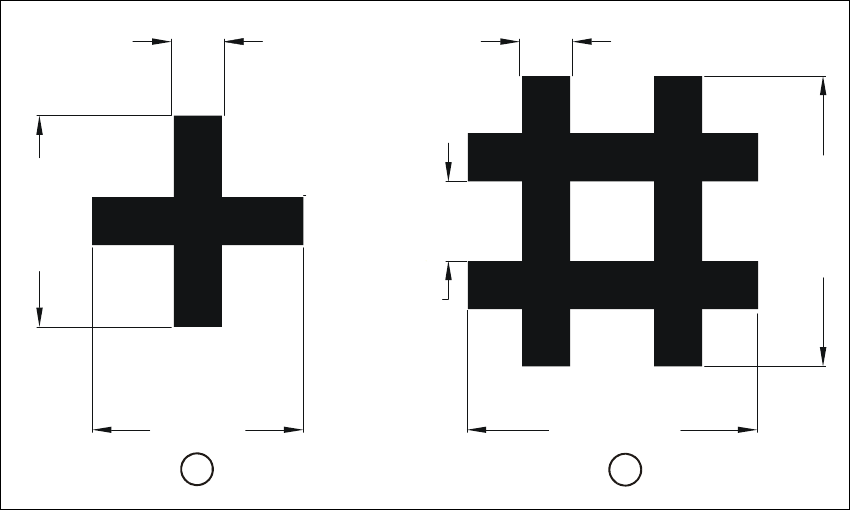
Fig. 6.2 - 3 Simple and double crosses with ideal dimensions
Key to Fig. 6.2 - 3
(1) Simple cross
(2) Double cross
6
The minimum dimensions for a fiducial in length (l) and width (b) depend on the line thickness (s)
and on the structure of the fiducial. 6
– Length (l) and width (b)
For the good fiducial recognition, the length and the width should be at least 0.9 mm with the
simple cross and 1.8 mm with the double cross. The ideal dimensions for the simple cross are
2.0 mm and for the double cross 2.75 mm. Under normal circumstances, length and width will
be equal.
– Line thickness (s)
The ideal line thickness for both fiducial types is 0.5 mm. The line thickness may vary, however,
according to standard structure widths and the type of fiducial. You should ensure that the line
is at least 0.3 mm thick, though.
– Line spacing (a)
Line spacing depends on the type of fiducial. Under no circumstances should line spacing fall
below 0.5 mm. For the double cross, the ideal spacing will be 0.75 mm.
l=2,75 mml=2,0 mm
b=2,0 mm
s=0,5 mm s=0,5 mm
b=2,75 mm
a=0,75 mm
2
1

User Manual S-23 HM 6 Vision functions
Software Version SR.405.xx 05/99 Issue 6.2 PCB vision system
179
– Thickness (d)
You should ensure, particularly with tin fiducials, that a warpage of more than 1/10 of the struc-
ture width is not exceeded. If this degree of warpage is exceeded, the fiducial may not be
evenly illuminated. This would lead to variations in reflection characteristics and unwanted re-
flections. Recognition of the fiducials will then no longer be assured.
Recommended fiducial dimensions 6
Analysis of the fiducial shapes 6
For tinned and higher dimensional stable structures, (a low degree of etching variation) full circles
or full squares may be regarded as very satisfactory fiducial shapes (the ratio of fiducial thickness
to presoldering thickness will be large!). If dimensional stability falls, the full circle should be pre-
ferred to the square. 6
As far as the fiducial shapes of simple and double cross are concerned, bright copper is advanta-
geous as long as oxidation has not advanced too far. 6
– Surface of the fiducials
Make sure that the surface of the fiducial is as level as possible and with little oxidation. Avoid
wetting the fiducial with solder-stop lacquer as this could result in lowering the contrast with the
background or produce unwanted reflections. Similar effects occur with tinned fiducials as well.
– Contrast of the fiducials
To ensure that fiducial recognition is of a high quality, select a high brightness contrast between
the fiducial and the base material; in other words, bright fiducials on a dark base material and
vice versa. For example, on a copper or tin background apply dark fiducials. In the case of ce-
ramic substrates with a bright surface and unsatisfactory reflective properties, it is often helpful
to precoat with a dark resistance material in order to improve contrast characteristics.
– Number of fiducials
When using ceramic substrates and small boards, tow fiducials will usually be sufficient. How-
ever, with larger boards it is recommended that three fiducials be defined. The individual fidu-
cials can vary in structure. You can simplify the recognition procedure if you use the same
structure for each fiducial.
Fiducial type Simple cross Double cross
Range Ideal Range Ideal
Length (l) 0.9 mm (min) 2.0 mm 1.8 mm (min) 2.75 mm
Width (b) 0.9 mm (min) 2.0 mm 1.8 mm (min) 2.75 mm
Line thickness (s) 0.3 - 1.4 mm 0.5 mm 0.3 - 0.75 mm 0.5 mm
Line spacing (a) — — 0.5 mm (min) 0.75 mm
Thickness (d) < 1/10 of the structure width < 1/10 of the structure width
Tab. 6.2 - 1