00191297-02.pdf - 第24页
1 Introduction User Manual S-23 HM 1.5 Description of the machine Software Version SR.405.xx 05/99 I ssue 22 The conc ept behin d the au tomati c placem ent sys tem 1 – with i ts stationary f eeder mod ules, – PCBs tha t…
User Manual S-23 HM 1 Introduction
Software Version SR.405.xx 05/99 Issue 1.5 Description of the machine
21
1.5 Description of the machine
1.5.1 Functional description
The automatic placement system is a high-performance placement system with two gantry axis
systems. A PCB vision system and a star-shaped 12-segment revolver head are mounted on each
gantry. Revolver placement heads equipped with a component vision system pick up the compo-
nents from stationary feeder modules and place them onto the PCB clamped in the PCB conveyor.1
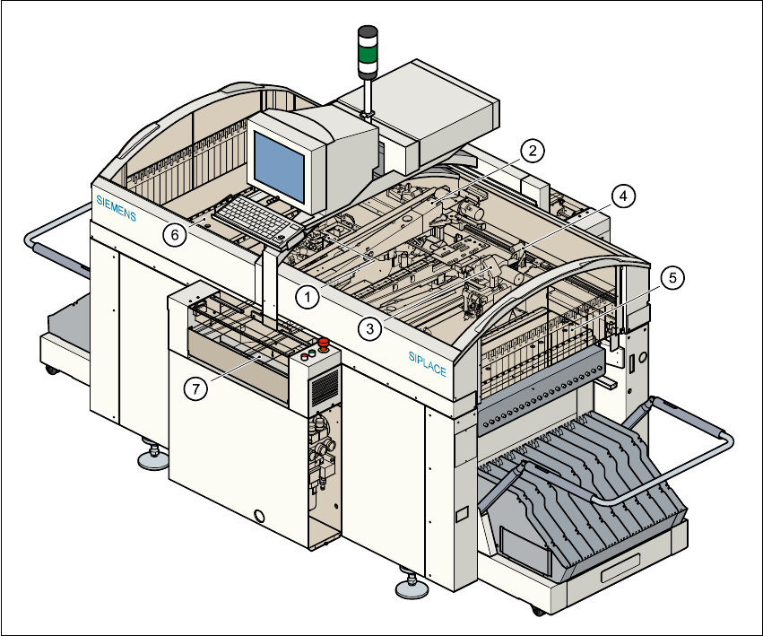
Fig. 1.5 - 1 Functional description of the placement system
(1) 12-segment revolver head /DLM1 with component vision camera (gantry 1)
(2) Gantry 1 with component vision camera
(3) 12-nozzle revolver head /DLM1 with component vision camera (gantry 2)
(4) Gantry 2 with PCB vision camera
(5) Stationary component supply (location 1)
(6) Stationary component supply (location 3)
(7) PCB conveyor (dual conveyor option)

1 Introduction User Manual S-23 HM
1.5 Description of the machine Software Version SR.405.xx 05/99 Issue
22
The concept behind the automatic placement system 1
– with its stationary feeder modules,
– PCBs that do not move during placement
– and positionable placement heads
has a number of significant benefits: 1
– For example, the flexible 12-segment revolver heads combined with automatic nozzle chang-
ers enable the nozzle configuration to be changed temporarily and automatically adapted to
receive different component sizes. You can also optimize the traversing paths and the place-
ment sequence.
– With stationary feeder modules, even the tiniest components are picked up reliably.
– The components cannot slip on the PCB during placement (as is often the case with moving
PCBs) since the PCB does not move.
– Sophisticated optical centering systems (vision systems) for components and PCBs also en-
sure high component positioning accuracy.
– Components can be topped up and tapes can be spliced without stopping the machine.
– Prepared component tables enable the placement system to be retooled without long stop-
pages.
1.5.2 Head Modularity concept (HM)
The abbreviation HM in the designation of the SIPLACE S-23 HM placement system stands for
Head Modularity. 1
The aim of this concept is to allow any combination of 6-nozzle and 12-nozzle revolver heads to
be used on the placement system. A simple head change procedure will enable the system to
be quickly adapted to the requirements of individual placement jobs. 1
The head modularity concept will be implemented in the next development stage. Placement sys-
tems supplied with the designation HM are designed to be compatible with the new concept. 1

User Manual S-23 HM 1 Introduction
Software Version SR.405.xx 05/99 Issue 1.5 Description of the machine
23
1.5.3 Technical data - machine overview
Range of components From 0402 to PLCC44, SO32, DRAM, µBGA
Maximum placement speed of the12-nozzle
revolver head (DLM1) 23,000 components/hour
Cycle time at the revolver head 125 ms, regardless of the type of component
Accuracy ± 90 µm at 4 sigma
± 67,5 µm at 3 sigma
PCB format 50 mm x 50 mm to 460 mm x 460 mm
2" x 2" to 18" x 18"
Option: up to 508 mm x 460 mm
up to 20" x 18 "
Feeding capacity Up to 80 tracks, each with 8 mm tapes
Feeder modules Tapes, bulk-cases
Operating system Microsoft Windows NT / RMOS
Combination options Inline or stand-alone
Space required 4 m² / module