00191297-02.pdf - 第293页
User Manual S-23 HM 6 Vision functions Software Vers ion SR.405.xx 05/99 Issue 6.7 Guidelines for Describing Package Form s 291 6.7.3 Shapes and possible measuring meth ods for rough (G) and fine centering (F) 6 Measu re…
6 Vision functions User Manual S-23 HM
6.7 Guidelines for Describing Package Forms Software Version SR.405.xx 05/99 Issue
290
6
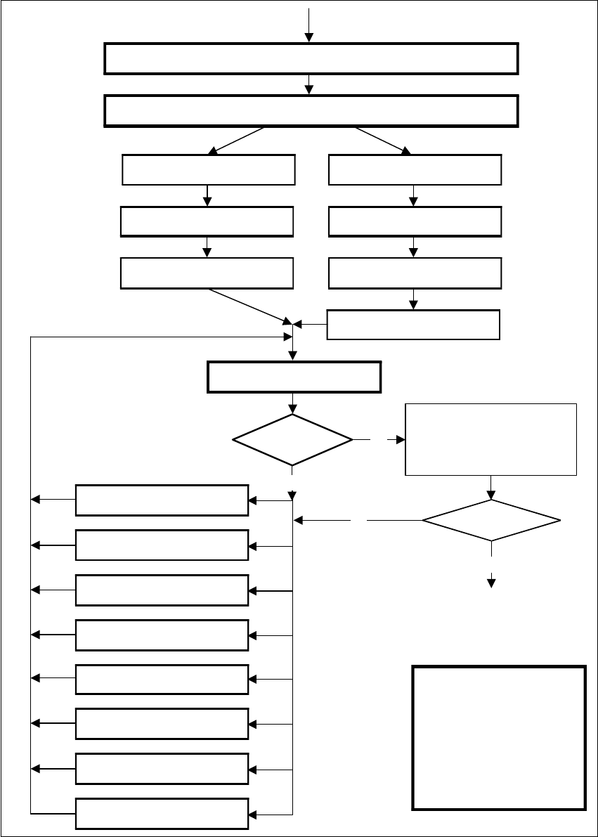
Fig. 6.7 - 4 Flow chart: ’Programming and testing a package form (GF)’, part 2 - station computer
Display component
Always identical?
No
No
Yes
Error message
occurred?
Yes
Check GF (component), press
Return for next meas. step
Check GF (component), press
Return for next meas. step
Important note:
The manipulation of
components at the station
must remain the exception,
rather than the rule.
In general, only a few
components have to be
changed.
1. Handling error: pick-up angle,
nozzle type, CO on nozzle etc.
2. Display component
3. Modify lighting
4. Modify measuring modes
and measuring parameters
5. Modify component dimension
6. Modify pin/ball contrast
7. Modify pin/ball dimensions
8. Program contrast
(program table)
Modify package form as required in "Vision system“ and "Test component“
Send program and set-up with this package form to the station and set up
Revolver head
Pick-up GF (component)
Pick&Place placement head
Pick up GF (component)
Measure component
Display component
Measure GF (component)
Repeat meas. process several
times (move component onto
nozzle to simulate picking up
different components)
and check results
User Manual S-23 HM 6 Vision functions
Software Version SR.405.xx 05/99 Issue 6.7 Guidelines for Describing Package Forms
291
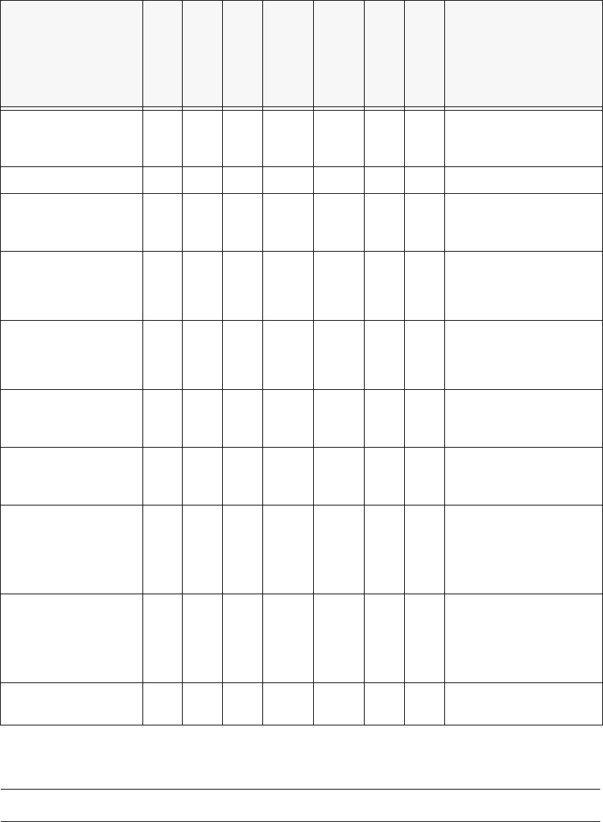
6.7.3 Shapes and possible measuring methods for rough (G) and fine centering (F)
6
Measurement of the spacing is replaced by measurement of the (standardized) lead deviation. 6
If one or more of the results are outside the tolerance, the component will not be placed. 6
Design
SIZE
ROW
CORNER
Lead
Combined
Lead Separate
analysis window
GRID
BALL
Result of the
last measuring step
PDC without lead G/F ∆X, ∆Y, (∆φ), Compo-
nent length, width, (qual-
ity)
PDC rounded image G/F F Angular tolerance
Small FDCs, e.g.
2 leads
G/F F ∆X, ∆Y, (∆φ), Compo-
nent length, width, (qual-
ity)
FDC, regular with
short rows of PINs
GFfour-
sided
F
Not
four-
sided
F
Max. deviation from the
spacing: ∆X, ∆Y, ∆φ,
(quality)
FDC, regular with long
rows of PINs
GFfour-
sided
F
Not
four-
sided
F
Max. deviation from the
spacing: ∆X, ∆Y, (∆φ),
quality
FDC irregular with
short rows of PINs
G(G)F F ∆X, ∆Y, number of PINs
(quality), max. deviation
from the spacing
FDC, irregular with
long rows of PINs
G(G)F F ∆X, ∆Y, number of PINs
(quality), max. deviation
from the spacing
FDC, irregular with
one row of PINs, sev-
eral PIN models or
spacings
GG F ∆X, ∆Y, (∆φ), standard-
ized lead deviation (qual-
ity)
Number of PINs, second-
ary offset
FDCs with circular
segment PIN arrange-
ments
(G) G F ∆X, ∆Y, (∆φ), standard-
ized lead deviation (qual-
ity)
Number of PINs, second-
ary offset
BGA, flip-chip G G F ∆X, ∆Y, (∆φ), spacing,
angle, quality)
Tab. 6.7.1 Component measuring methods
6 Vision functions User Manual S-23 HM
6.7 Guidelines for Describing Package Forms Software Version SR.405.xx 05/99 Issue
292
If the component cannot be centered correctly, additional measuring methods may be omitted.
You should, however, carry out all the rough centering steps since these reduce the size of the
measuring window. 6
– In the ’Test component’ menu, the components are optically centered in the individual measur-
ing steps, via the ’Check component’ function, but the results are not output.
– In the ’Test component’ menu, the components are optically centered in the individual measur-
ing steps, via the ’Measure component’ function, but the results are not output.
– If the components are larger than 32 mm x 32 mm, a multiple measurement will be carried out
automatically in the vision system.