00191297-02.pdf - 第319页
User Manual SIPLAC E S-23 HM 7 What s hould you do ... Software V ersion SR.405.xx 05/99 Issue 7.5 When you, as an operator , carry out a walk-through inspection 317 7 Fig. 7.5 - 2 Dividing plates in the t ape container …

7 What should you do ... User Manual SIPLACE S-23 HM
7.5 When you, as an operator, carry out a walk-through inspection Software Version SR.405.xx 05/99 Issue
316
È Check to see if the additional plastic guides are being used on the feeder modules that are in-
tended for tapes of different widths.
È Check the position of the stopper on the PCB transport.
Always position the stopper so that it is not placed within any cut-outs or recesses in the PCB.
È Check the magnetic supports on the lifting table. They must be arranged so that they do not
collide with components on the bottom of the PCBs.
NOTE
Splice the tapes early enough so that the feeder modules do not become empty or you will
experience prolonged down times.
However, do not splice the tapes too early because if you wind the end of the old tape onto
the new reel after splicing, the reel holding the new tape may become overfilled and the tape
will slip off the reel and become tangled up. This will again result in pick-up errors and pro-
longed down times. 7
È Place insertable shafts into the tape container when using large tape reels.
È Insert the dividing plates as shown in Fig. 7.5 - 2 and remember that the smallest division of the
tape container is a 2x division. This will help avoid placement errors.
7
7
7
User Manual SIPLACE S-23 HM 7 What should you do ...
Software Version SR.405.xx 05/99 Issue 7.5 When you, as an operator, carry out a walk-through inspection
317
7
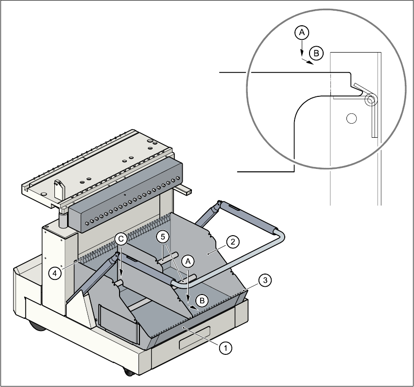
Fig. 7.5 - 2 Dividing plates in the tape container
Key to Fig. 7.5 - 2
(1) Tape container
(2) Dividing plate
(3) Guide rail for the dividing plates on the front of the container
(4) Guide rail for the dividing plates on the back of the container
(5) Supporting rod for the dividing plates
Steps for Fig. 7.5 - 2
A Insert the dividing plate with the nose under the guide rail on the front of the container.
B Push the dividing plate in direction (B).
C Engage the dividing plate on the supporting rod (5).
7 What should you do ... User Manual SIPLACE S-23 HM
7.6 Preliminary set-up of the placement station Software Version SR.405.xx 05/99 Issue
318
7.6 Preliminary set-up of the placement station
Carry out the following steps to complete the preliminary set-up of the placement station.
È Remove the tapes from the feeder modules and vacuum the surfaces of the modules and the
area around the tape guide clean with the vacuum cleaner.
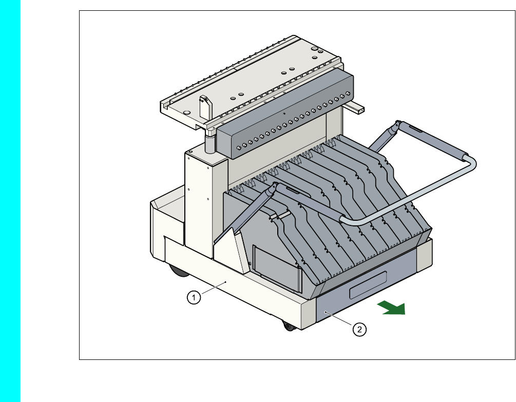
È Remove the cover foil from the tape waste containers (item 2).
7
Fig. 7.6 - 1 Emptying the tape waste container
(1) Component changeover table, mobile (2) Waste tape container, extendible
7
È Clean the supporting surfaces of the feeder modules with a cloth moistened with alcohol.
È Apply a small amount of WD40 corrosion protection to the supporting surfaces with a lint-free
cloth.
È Use a vacuum cleaner or use a brush with short bristles to remove loose components from the
component tables.