00191297-02.pdf - 第34页
1 Introduction User Manual S-23 HM 1.10 Setting up the placement system Software Version SR.405.xx 05/99 Issue 32 1.10.6 Setting up the pla cement syst em È Raise the placemen t system using th e fork- lift truck and adj…
User Manual S-23 HM 1 Introduction
Software Version SR.405.xx 05/99 Issue 1.10 Setting up the placement system
31
1.10.2 Transport configuration and transportation
The following components are not installed when the placement system is delivered from the fac-
tory: 1
– keyboards
–monitors
– fault indicator lamps and
– component tables
È Install the dismantled components for commissioning.
È Use a fork-lift truck to transport the placement system with a minimum fork length of 1600 mm.
È Attach the fork-lift truck only at the indicated points.
1.10.3 Quality of the foundation
È Ensure that
– you set up the placement system on a firm and non-vibrating foundation.
– the load bearing capacity per unit area of the foundation is greater than 1000 kg/m².
1.10.4 Compressed air supply
– The pressure of the compressed air supply must be 5.5 bar min (max. permissible value
10 bar).
– The compressed air must conform to the above specification.
This can be achieved with 1
– oil-free compressors, e.g. Atlas, Copco type ZR4
– compressed air washer/driers
– micro-filters, series X, e.g. from Zander
1.10.5 Power supply
– The power socket must be fused with the following fuse ratings:
3 x 16 A for 3 x 400 VAC 1
3 x 32 A for 3 x 208 VAC 1

1 Introduction User Manual S-23 HM
1.10 Setting up the placement system Software Version SR.405.xx 05/99 Issue
32
1.10.6 Setting up the placement system
È Raise the placement system using the fork-lift truck and adjust the feet until there is a gap of
830 mm between the top edge of the PCB conveyors and the bottom edge of the feet.
È Leave a gap of 1 to 3 mm between the PCB conveyors of the placement system.
È Use a cord pulled tight to ensure that all the placement systems are exactly in line with one
another.
È Adjust each placement system using a spirit level with an accuracy of 0.02 mm/m.
È Lock the feet in position.
È Check the placement system again using the spirit level and correct the settings, if necessary.
CAUTION
Make sure that you remove all the shipping braces from the placement system. 1
È Fit any components that were dismantled for dispatch.
È Connect all the electrical and pneumatic lines.
RISK OF DEATH
The electrical connection work MUST be carried out only by appropriately trained and certi-
fied personnel. 1
User Manual S-23 HM 1 Introduction
Software Version SR.405.xx 05/99 Issue 1.11 Overview of the modules - controls
33
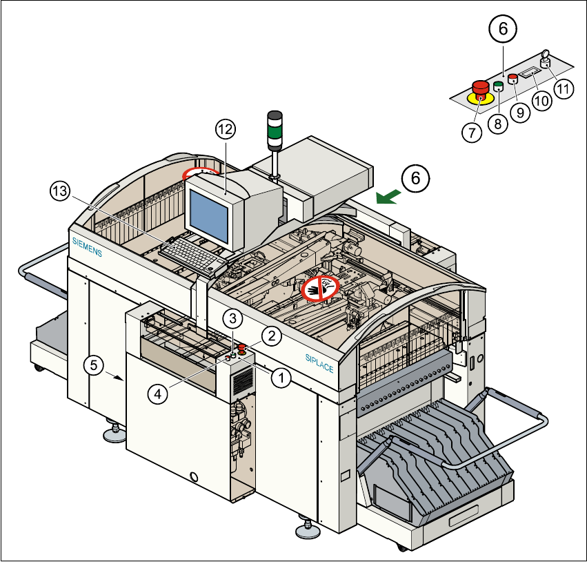
1.11 Overview of the modules - controls
1.11.1 Controls
1
Fig. 1.11 - 1 Overview of the modules - controls
(1) Operator panel, input conveyor (2) Emerg. stop mushroom-head push-button
(3) Start button (white) (4) Stop button (black)
(5) Main power switch (6) Operator panel, output conveyor
(7) Emerg. stop mushroom-head push-button (8) Start button (white)
(9) Stop button (black) (10) Component counter
(11) Key-operated switch (12) Touchscreen monitor
(13) Keyboard with trackball 1