00191297-02.pdf - 第372页
11 Station extensions / options User Manual S-23 H M 11.1 Nozzle changer Software Vers ion SR.405.xx 05/99 I ssue 370 11 Fig. 1 1.1 - 1 Nozz le changer ov erview - revolver head Key to Fig. 1 1 .1 - 1 (1) Maga zine (2) N…
User Manual S-23 HM 11 Station extensions / options
Software Version SR.405.xx 05/99 Issue 11.1 Nozzle changer
369
11 Station extensions / options
11.1 Nozzle changer
11.1.1 Overview
The placement system is supplied as standard with two revolver heads. As an option, a nozzle
changer can be installed for each revolver head. 11
The nozzle changer consists of at least one, and up to seven magazines, each with twelve nozzle
garages (see Fig. 11.1 - 1). The magazines are seated on a common support and each magazine
is centered using two parallel pins and fixed in place with a screw. 11
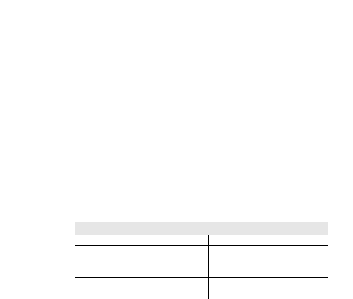
11.1.2 Technical data
11
Nozzle changer for the revolver head
Dimensions (length x width x height) 560 mm x 60 mm x 46 mm
Number of nozzle garages Min. 12 / max. 84
Nozzle types 9xx
Time required to open and close the locking plate < 200 ms
Capacity of the reject box Approx. 50 nozzles
Pneumatic circuit Compressed air line 5.3 bar
11 Station extensions / options User Manual S-23 HM
11.1 Nozzle changer Software Version SR.405.xx 05/99 Issue
370
11
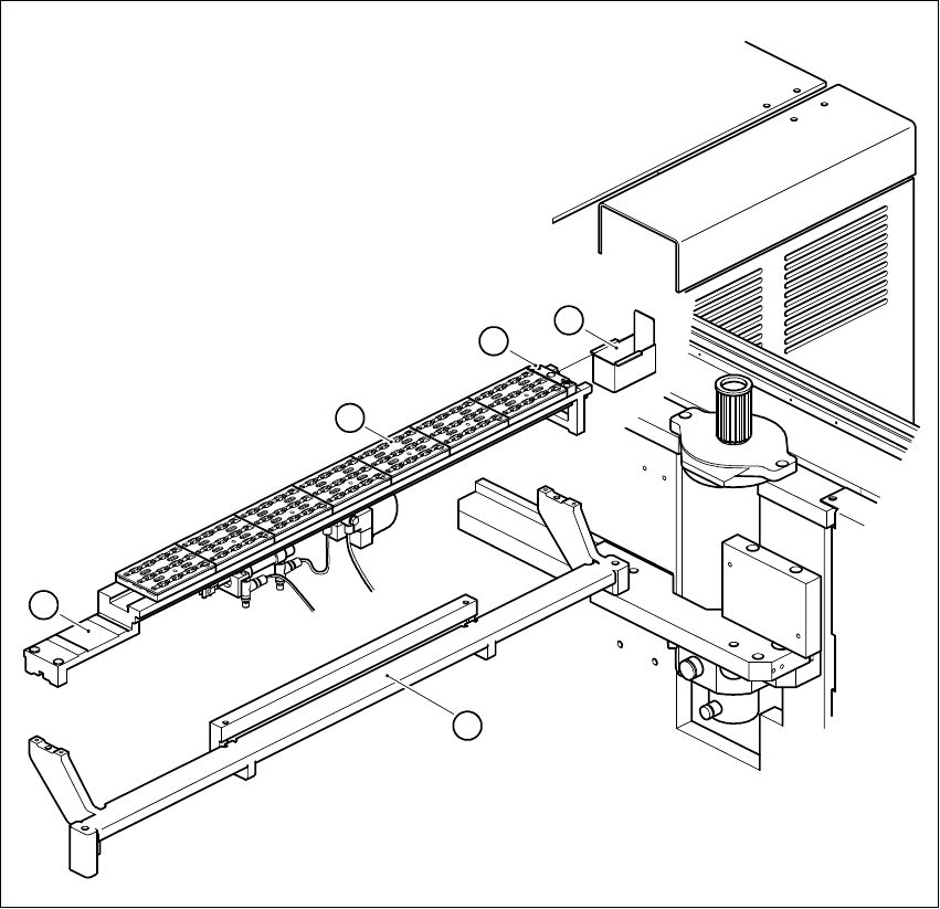
Fig. 11.1 - 1 Nozzle changer overview - revolver head
Key to Fig. 11.1 - 1
(1) Magazine (2) Nozzle discarding device
(3) Container for discarded nozzles (4) Nozzle changer base
(5) Nozzle changer support 11
4
1
2
3
5

User Manual S-23 HM 11 Station extensions / options
Software Version SR.405.xx 05/99 Issue 11.1 Nozzle changer
371
11.1.3 Mode of operation
The nozzles are seated in nozzle garages and are held in place by a movable locking plate. The
locking plate can be moved 6 mm by a pneumatic cylinder. All the nozzles are either clamped or
released, depending on the position of the plate. The default position of the locking plate, i.e. if
there is no nozzle change in progress, is "closed". 11
There is a positioning fiducial for position detection on each magazine of the nozzle changer. The
magazine locations are identified by numbers 1 to 7 on the nozzle changer. The nozzle garages
in the magazines are numbered consecutively from 1 to 12 (see Fig. 11.1 - 2). 11
PLEASE NOTE 11
Special magazines are available upon request (contact Siemens PL EA 1E for details) and will be
numbered differently. 11
Picking up a nozzle 11
– The revolver head z axis moves down.
– The locking plate (item 3 in Fig. 11.1 - 2) opens and releases the nozzle garages.
– The nozzle is picked up by the sleeve of the revolver head.
– The z axis moves up.
Setting down a nozzle 11
– The locking plate (item 3 in Fig. 11.1 - 2) opens and releases the nozzle garages.
– The revolver head z axis moves down and sets the nozzle down.
– The locking plate closes.
– The revolver head z axis moves up.
Discarding defective nozzles 11
– The revolver head z axis moves down 14 mm towards the discarding device (item 2 in Fig. 11.1
- 1) and thus moves the defective nozzle into the hole in the discarding device.
– The z axis moves up again and the nozzle is stripped from the sleeve by spring wires.
– The nozzle drops into the container (item 3 in Fig. 11.1 - 1).