00191297-02.pdf - 第64页
2 Operational Safety User Manual S-23 HM 2.2 Safety equipment Software Vers ion SR.405.xx 05/ 99 Issue 64 2.2 Safety equipme nt 2.2.1 Protective covers 2 Fig. 2.2 - 1 SIPLACE S-23 HM safety equipment Key to Fig. 2 .2 - 1…
User Manual S-23 HM 2 Operational Safety
Software Version SR.405.xx 05/99 Issue 2.1 Safety instructions
63
Fig. 2.1 - 8 Label: ‘Laser radiation...’
Fig. 2.1 - 9 Label: ’Caution ...’
2.1.9 Safety instructions for changing the component table
Changing the component table is described in section 7.8.1 from page 321 . Always obey the fol-
lowing safety instructions to prevent injury or damage to the automatic placement system. 2
WARNING
When you change the component table, always follow the sequence for removing the plugs from
the communication unit and then connecting them again as described below. If you do not follow
the specified order, faults may occur in the component table. 2
WARNING
Move the portal out of the range of the component table over the PCB transport. This will prevent
the possibility of a head crash. 2
DANGER
Press the emergency stop mushroom-head push-button. The gantry axes are switched off and
isolated. This will prevent the gantries starting up accidentally, thus preventing the associated risk
of injury or damage. 2
Laser radiation
Do not look into the beam
Laser class 2
Caution
Laser radiation if the cover is opened
and the safety interlock is bypassed
Do not look into the beam
2 Operational Safety User Manual S-23 HM
2.2 Safety equipment Software Version SR.405.xx 05/99 Issue
64
2.2 Safety equipment
2.2.1 Protective covers
2
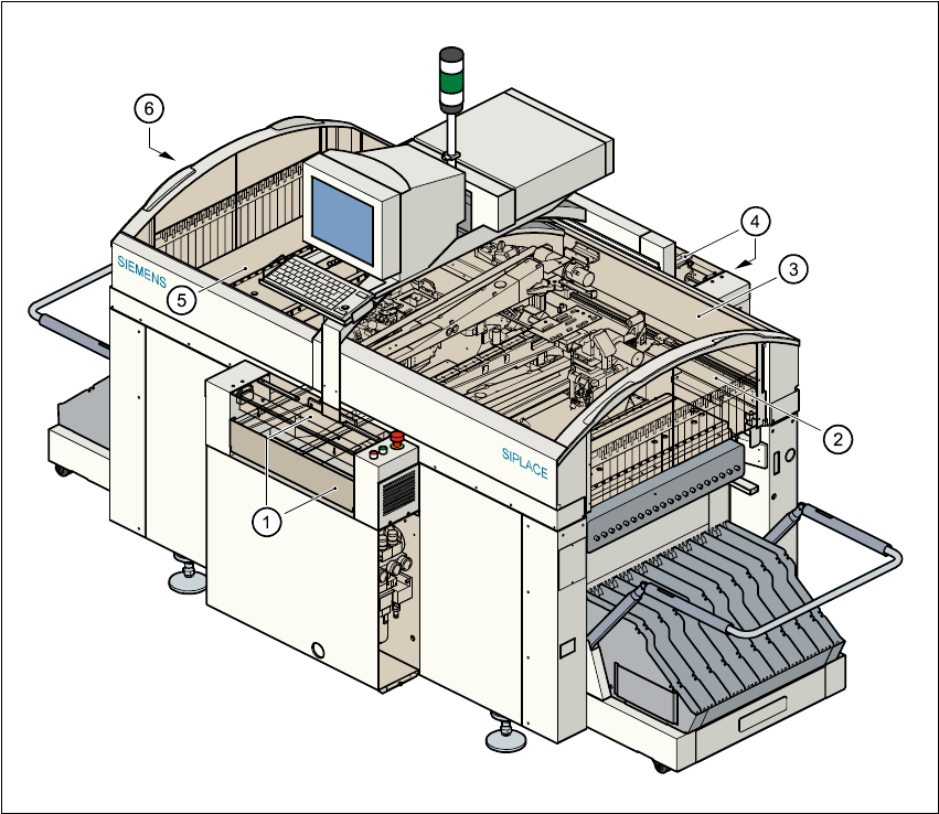
Fig. 2.2 - 1 SIPLACE S-23 HM safety equipment
Key to Fig. 2.2 - 1
(1) Cover and guard on the input belt
(2) Safety panels, righthand side
(3) Protective cover
(4) Cover and guard on the output conveyor
(5) Protective cover
(6) Safety panels, lefthand side
User Manual S-23 HM 2 Operational Safety
Software Version SR.405.xx 05/99 Issue 2.2 Safety equipment
65
2.2.1.1 General
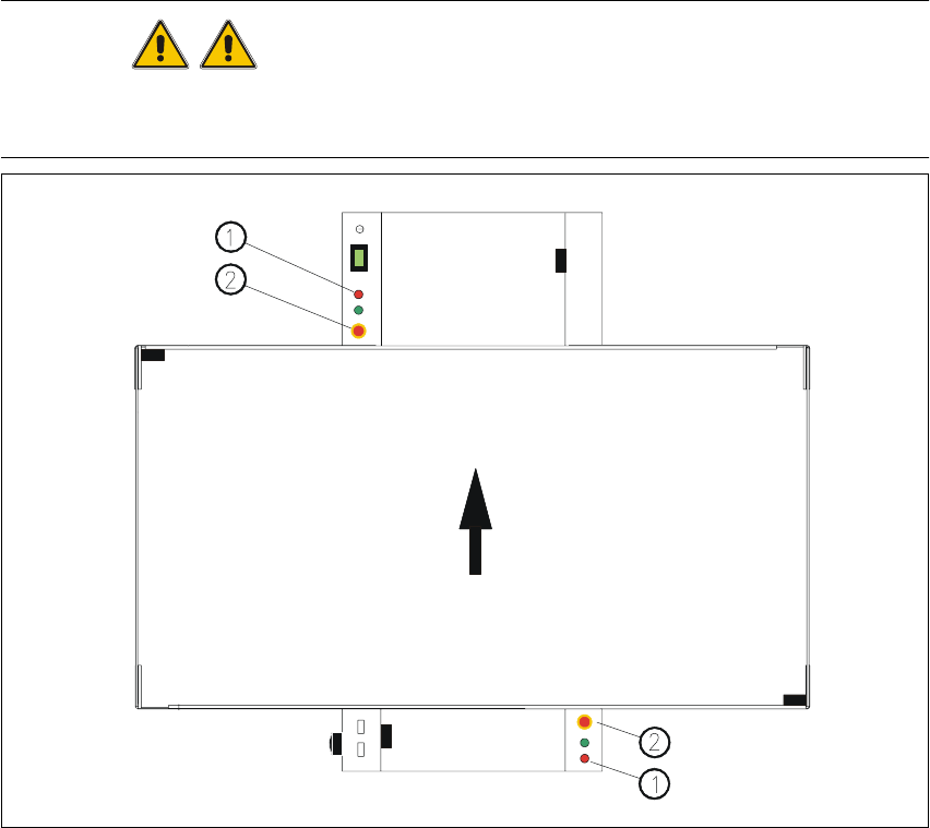
The gantry positioning range is covered by two protective covers. If you want to open the protec-
tive covers, first press the Stop button (item 1 in Fig. 2.2 - 2) or the emergency stop mushroom-
head push-button (item 2 in Fig. 2.2 - 2). The power to the gantry axes will be switched off and the
gantries will stop immediately. 2
If you open one of the protective covers or a guard on the incoming or outgoing conveyor, the
power to the gantry axes will be switched off and they will stop immediately. 2
If the key switch is closed (position I), you can continue to pace the star at reduced speed while
the protective covers are open. 2
Placement will stop if you press the emergency stop button. You can then either cancel or continue
placement of the PCB. The protective covers at the sides can be opened in order to refill with com-
ponents when the machine has stopped. 2
WARNING
The protective covers must only be opened, with the key switch closed (position I), by appropri-
ately qualified and trained personnel. 2
Fig. 2.2 - 2 Stop and emergency stop mushroom-head push-buttons
(1) Stop button (2) Emergency stop mushroom-head push-button 2