00191297-02.pdf - 第67页
User Manual S-23 HM 2 Operational Safety Software Vers ion SR.405.xx 05/99 Iss ue 2.2 Safety equipment 67 2.2.3 EMERGENCY STO P mushroom-head push- buttons, protective cover switches ... 2 Fig. 2.2 - 4 Location of the bu…
2 Operational Safety User Manual S-23 HM
2.2 Safety equipment Software Version SR.405.xx 05/99 Issue
66
2.2.2 Guard on the input / output conveyor
DANGER
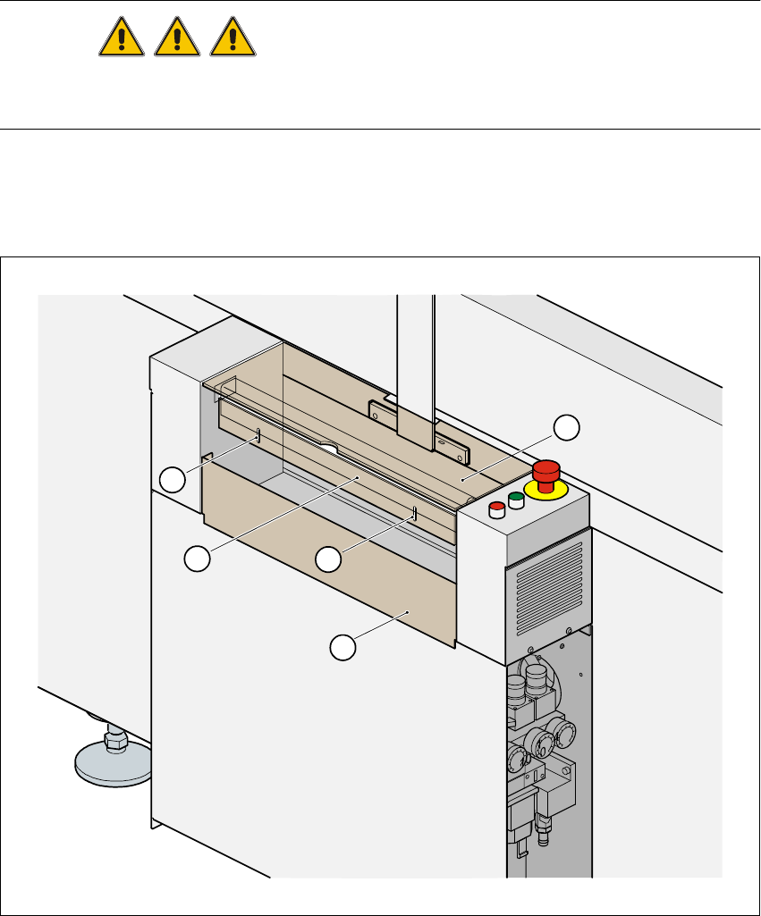
The guard must always be set to the height of the PCB to be processed. Ensure that the gap be-
tween the guard and the safety bar is as small as possible. 2
Guards are fitted on the input and output belts of the PCB conveyor. 2
The height of the guard must be set using the slots so that the processed PCB can travel through.2
2
Fig. 2.2 - 3 Guard on SIPLACE S-23 HM
(1) Safety bar (fixed) (2) Guard (adjustable) 2
(3) Slots for adjusting the height (4) Cover 2
4
1
2
3
3
User Manual S-23 HM 2 Operational Safety
Software Version SR.405.xx 05/99 Issue 2.2 Safety equipment
67
2.2.3 EMERGENCY STOP mushroom-head push-buttons, protective cover
switches ...
2
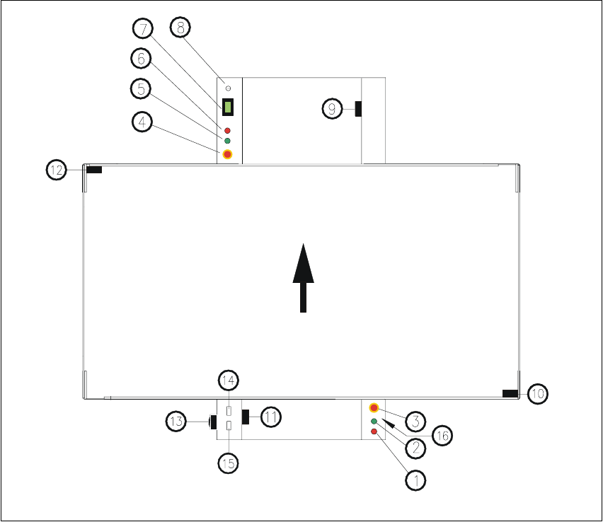
Fig. 2.2 - 4 Location of the buttons and protective contactor combinations K1, K2
Key to Fig. 2.2 - 4
(1) Stop button
(2) Start button
(3) EMERGENCY STOP mushroom-head push-button
(4) EMERGENCY STOP mushroom-head push-button
(5) Start button
(6) Stop button
(7) Component counter
(8) Key switch open: position 0 for normal mode
Key switch closed: position I for service purposes
2 Operational Safety User Manual S-23 HM
2.2 Safety equipment Software Version SR.405.xx 05/99 Issue
68
(9) Protective cover switch (output conveyor, 00303617-xx)
(10) Protective cover switch (right, 00321417-xx)
(11) Protective cover switch (input conveyor, 00303614-xx)
(12) Protective cover switch (left, 00321416-xx)
(13) Main power switch
(14) Protective contactor combination K1
(15) Protective contactor combination K2
(16) Compressed air unit
2.2.3.1 Functional description
EMERGENCY STOP mushroom-head push-button 2
When the emergency stop mushroom-head push-button is pressed (item 3 or item 4. in
Fig. 2.2 - 4), the motor voltage to the gantry axes is switched off. The gantry axes are no longer
powered, and thus are not dangerous. 2
PLEASE NOTE
Placement is interrupted and can then either be continued or cancelled once the system is working
correctly again. 2
Protective cover switch 2
If one of the protective covers is opened (see item 9, 10, 11 or 12 in Fig. 2.2 - 4), the gantry axes
will stop immediately. They are no longer powered, and thus are not dangerous. 2
Key switch 2
If the key switch (item 8 in Fig. 2.2 - 4) is closed (position I), the star can still be paced at low speed
while the protective covers are open. The gantry axes are no longer powered, and thus are not
dangerous. 2
PLEASE NOTE
The key switch remains open for normal mode, i.e. in the 0 position. 2
WARNING
The protective covers must only be opened, with the key switch closed (position I), by appropri-
ately qualified and trained personnel. 2