00191297-02.pdf - 第92页
3 Introduction and Ba sic Concepts User Manual SIPLACE S-23 HM 3.1 Machine Displays and Controls Software Version SR.405.xx 05/99 Issue 90 3.1.5 St ation Computer The statio n co mput er is a des ktop m odel a nd i s equ…

User Manual SIPLACE S-23 HM 3 Introduction and Basic Concepts
Software Version SR.405.xx 05/99 Issue 3.1 Machine Displays and Controls
89
3.1.3 Main Fault Indicator
The main fault indicator (see Figure 3.1 - 1) contains 2 fault indicator lights (white) together with
an operating indicator light (green) 3
The operating indicator light is located between the two fault indicator lights. This indicates
whether the machine is in production or wait mode. 3
The nature and location of any malfunction can be identified using the operating indicator light
(flashing, glowing etc.) and the two fault indicator lights. 3
The following section describes the information provided by the two fault indicator lights. 3
3.1.3.1 Functions
General Operating Statuses: 3
– Operating indicator light continuously illuminated
The machine is operating.
– Operating indicator light flashes
The machine is waiting for a PCB in the input conveyor or is waiting for the output conveyor to
become free.
– Fault light flashes
One or more tracks are empty at the feeder location of the gantry in question.
However, the machine will process any components present.
– Fault light continuously illuminated
An error has occured at the gantry in question--> the machine has stopped.
– Both lights continuously illuminated
An error has occurred which affects the entire machine--> the machine has stopped.
3.1.4 Barcode Reader
The barcode reader is available as an option. It is very helpful, particularly under production
conditions, since component barcodes on component reels and track barcodes can be read in
quickly and reliably from the barcode strip on the machine.
An acoustic signal sounds each time a data record is successfully read in.
NOTE
For a detailed description of the function, connection and operation of the bar code reader, refer
to chapter 11 Station extensions / options. 3

3 Introduction and Basic Concepts User Manual SIPLACE S-23 HM
3.1 Machine Displays and Controls Software Version SR.405.xx 05/99 Issue
90
3.1.5 Station Computer
The station computer is a desktop model and is equipped with a 3
1
/
2
" floppy drive and a CD-ROM
drive. The operating system is Microsoft Windows NT 4.0 and the graphical user interface for the
placement system is based on the Windows standard. 3
3.1.6 Monitor
The color monitor with integrated touch screen acts as the display and operating tool for the
graphic user interface of the SC software. You select functions using your finger which guides the
mouse pointer over the screen itself. 3
Actions can be executed by touching the corresponding object (e.g. button or icon) on the
screen. 3
CAUTION
Protect the monitor from humidity and excessive heat (sunlight, room heating).
Never obstruct the ventilation slots.
Never try to remove the cover.
Make sure that no moisture is able to penetrate the inside of the monitor.
Make sure that the operating voltage is set correctly.
Make sure that the brightness and contrast of the screen display are set to medium values since
these greatly prolong the lifetime of the screen. 3
3
NOTE
Each monitor is supplied with a separate User Manual and you should follow the warnings and
safety instructions it contains.
Please refer to the Manual for a description of the connections and setting options. By default, the
resolution of the screen display is set to 640 x 480 pixels. 3
3
3
User Manual SIPLACE S-23 HM 3 Introduction and Basic Concepts
Software Version SR.405.xx 05/99 Issue 3.1 Machine Displays and Controls
91
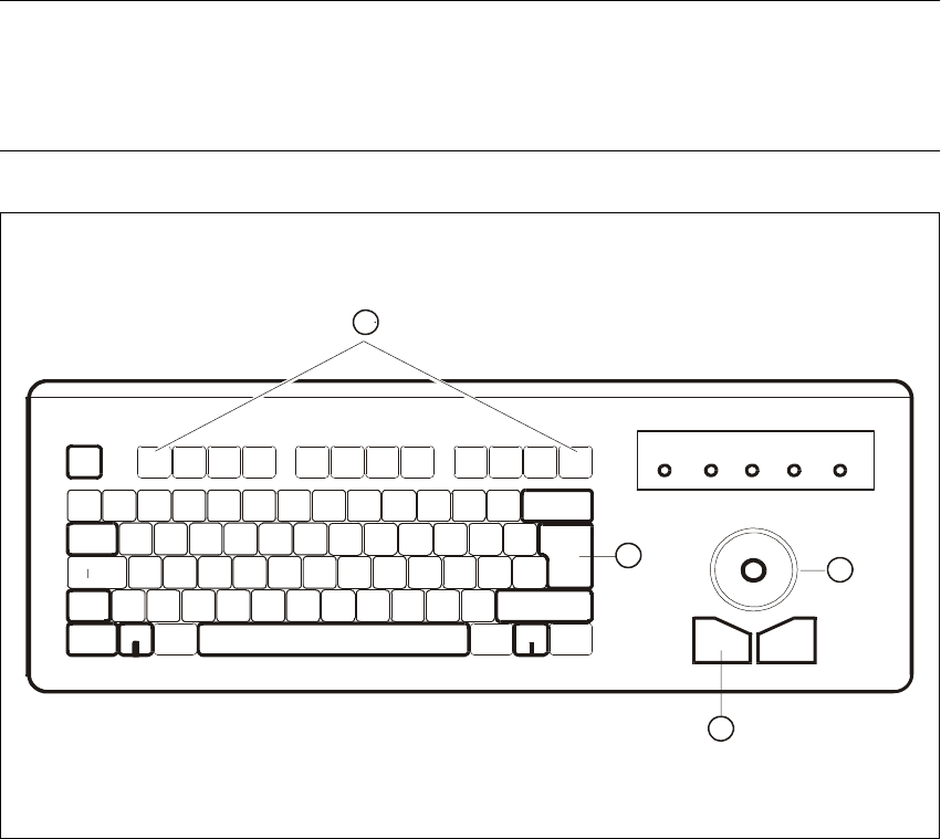
3.1.7 Keyboard
The ultra-flat keyboard installed is IBM-compatible. It is equipped with integrated trackball and
mouse button. 3
The keyboard and trackball act as the standard operating tools for the graphic user interface of
the SC software. 3
NOTE
A separate User Manual is supplied for the keyboards. These contain a description of the keys,
indicators and setting options.
Please respect the warnings and safety instructions contained in this Manual. 3
3
Fig. 3.1 - 3 Keyboard
Key to Figure 3.1 - 3
(1) RETURN key
(2) Left mouse button
(3) Trackball
(4) Function keys F1 to F12
LASER
PROG
ESC
TAB
1
Q
F1
CTRL
Scroll Pad
Trackball
Num Caps
F2 F3 F4 F5 F6 F7 F8 F9 F10 F11 F12
1
2
3
4