Maintenance Schedule保养计划 - 第12页
Vision XP+ V AC / XP+ / XP / XS Page 21 2 Mainte nance 2.4 Proces s Chamber Service Instructions V ersion 1.3 2.4.7 Replacing the S eals Fig. 2-1 1 R e placing the P rocess Chamb e r Seals Fig. 2-12 Replacing th e Proces…
Page 20 Vision XP+ VAC / XP+ / XP / XS
2 Maintenance
2.4 Process Chamber
Service Instructions
Version 1.3
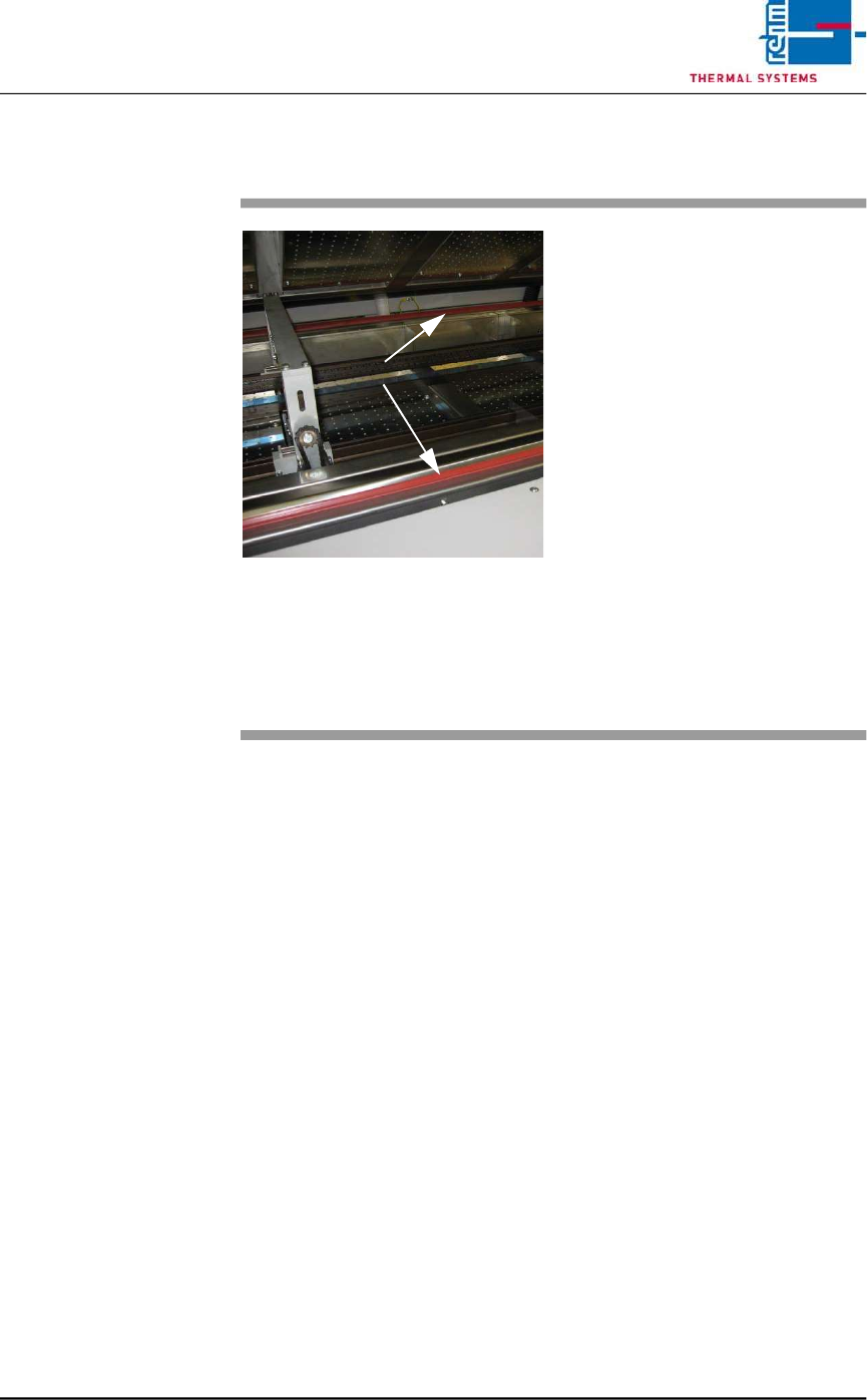
2.4.6 Cleaning the Seal
Fig. 2-10 Cleaning the Process Chamber
Seal
The seals must be clean and un-
damaged in order to assure reliable
production.
Consumable materials:
• Appropriate cleaning agent
• Rags
Procedure:
1. Raise the process chamber.
2. Clean the process chamber
seals with industrial alcohol and
a rag.
3. Clean all contamination from
the sheet metal panel at the
mating side of the seal.
4. The seals at the system’s inlet
and outlet must be cleaned
using the same procedure.
Seals
Vision XP+ VAC / XP+ / XP / XS Page 21
2 Maintenance
2.4 Process Chamber
Service Instructions
Version 1.3
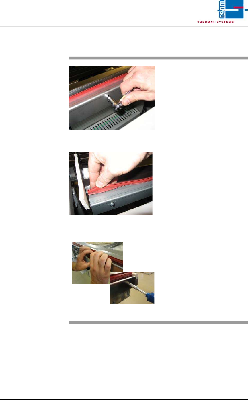
2.4.7 Replacing the Seals
Fig. 2-11 Replacing the Process Chamber
Seals
Fig. 2-12 Replacing the Process Chamber
Seals
Fig. 2-13 Replacing the Process Chamber
Seals
Consumable materials:
detergent water
Procedure:
1. The seal can be pulled by hand
from the metal bracket.
2. Then clean the metal bracket
inside with detergent water.
3. Loosen the screws slightly
4. Now, the seal can be pressed
again into the metal bracket.
5. Press down the holder sheet
with the hand and tighten the
screws again.
Page 22 Vision XP+ VAC / XP+ / XP / XS
2 Maintenance
2.5 Cooling Tract
Service Instructions
Version 1.3
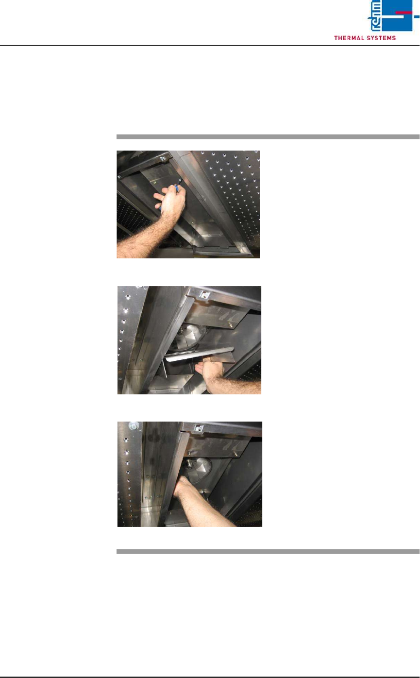
2.5 Cooling Tract
2.5.1 Cleaning the Cooling zone (passive area)
Fig. 2-14 Cover for Suction Chamber
Fig. 2-15 Sheet Metal Cover on Impeller
Fig. 2-16 Fan Impeller
The cooling zone can be dismantled
as described below. The individual
parts (e.g. nozzle field etc.) are
cleaned in a rinsing bath, or with
oven cleaner and rags.
Consumable materials, tools:
• Oven cleaner CF 1
• Rags
• Or rinsing bath
Procedure:
1. Loosen the screws on the
nozzle sheet and lift it out.
2. Unscrew suction chamber
cover (see Fig. 2-14).
3. Remove the sheet metal cover
from the impeller (see Fig. 2-
15).
4. The fan impeller is now
exposed and can be inspected,
and cleaned with oven cleaner
and rags (see Fig. 2-16).