Maintenance Schedule保养计划 - 第17页
Page 26 Vision XP+ V AC / XP + / XP / XS 2 Mainte nance 2.5 Co oling T ract Service Instructions V ersion 1.3 2.5.5 Inspecting and C leaning the Fan Impeller Fig. 2-25 Cleaning the Fan Impeller The fan impellers are loca…
Vision XP+ VAC / XP+ / XP / XS Page 25
2 Maintenance
2.5 Cooling Tract
Service Instructions
Version 1.3
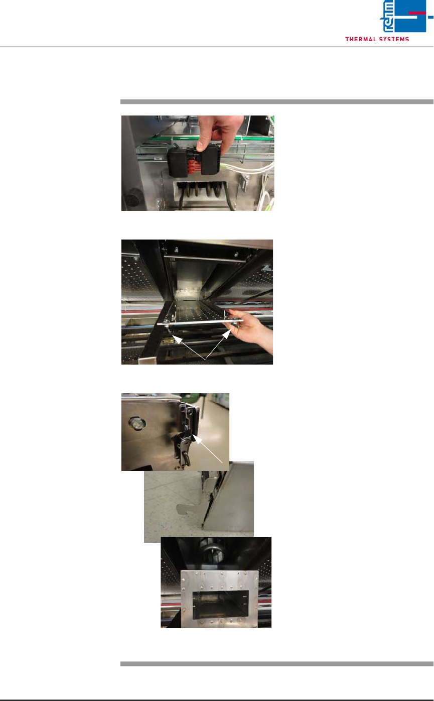
2.5.4 Clean cooling module 1 VXP+
Fig. 2-22 Disconnect power supply
Fig. 2-23 Lower nozzle field
Fig. 2-24 Unlatch, remove the cooling modu-
le
Consumables, tools:
• Oven cleaner
• Cleaning rags
• Cleaning bath
Procedure:
1. First disconnect the electric
heater supply at the back of
the plant. Then pull out the
heater at the back.
2. Now remove cooling module 1
at the front of the machine for
cleaning, as follows.
3. Rotate the wing screws on the
right and left of the nozzle field
by 90° and lower the nozzle
field for cleaning.
4. Unlatch the cooler cassette,
lift and pull out towards the
front.
5. Place the cooler cassette in the
cleaning bath.
6. Re-fit the cleaned cooler cas-
sette.
7. Check the water through-flow at
the flow meter.
8. Push the heater at the back of
the machine back in and plug in
the power supply.
Page 26 Vision XP+ VAC / XP+ / XP / XS
2 Maintenance
2.5 Cooling Tract
Service Instructions
Version 1.3
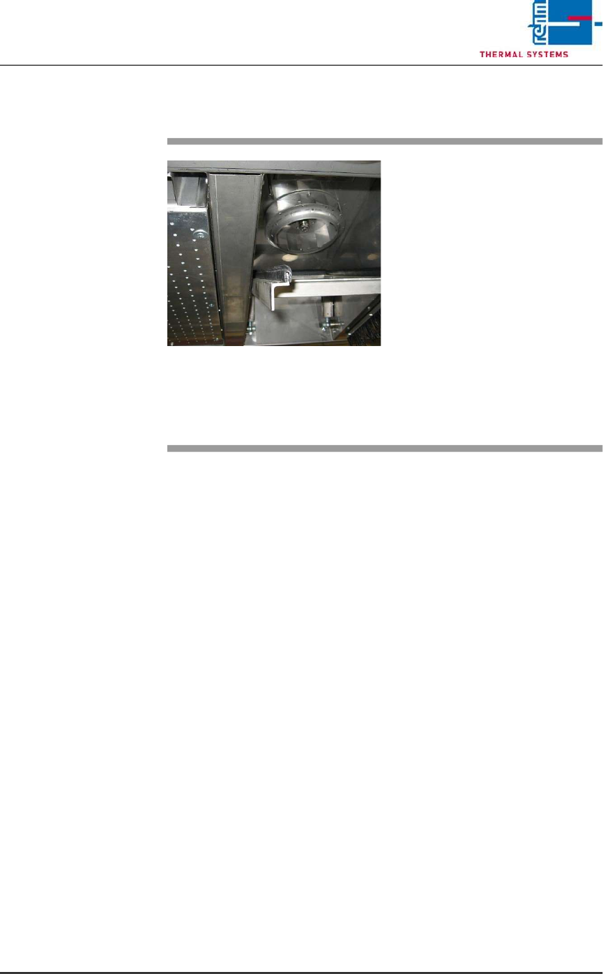
2.5.5 Inspecting and Cleaning the Fan Impeller
Fig. 2-25 Cleaning the Fan Impeller
The fan impellers are located in the
process chamber behind the cooler
cartridges.
Consumable materials, tools:
• Oven cleaner
• Rags
Procedure:
1. Remove the cooler cartridge
(see instructions in chapter
2.5.2).
2. Inspect the fan impellers for
contamination, and clean with
oven cleaner and rags if
necessary.
Vision XP+ VAC / XP+ / XP / XS Page 27
2 Maintenance
2.5 Cooling Tract
Service Instructions
Version 1.3
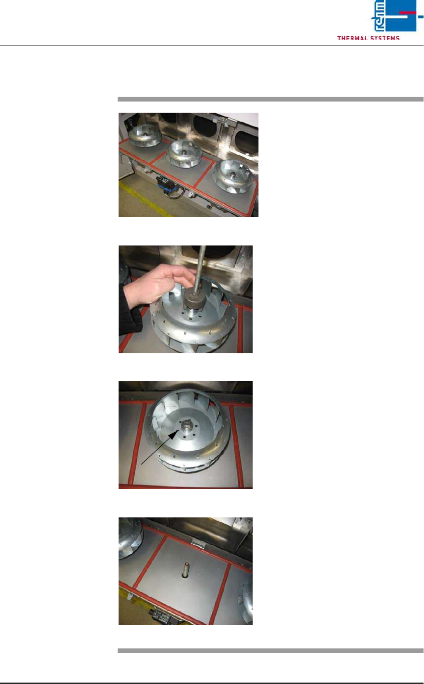
2.5.6 Replacing the Fan Impeller
Fig. 2-26 Replacing Fan Impeller (step 1)
Fig. 2-27 Replacing Fan Impeller (step 2)
Fig. 2-28 Replacing Fan Impeller (step 3
Fig. 2-29 Replacing Fan Impeller (step 4)
Consumable materials, tools:
• 17 mm box wrench or open-end
wrench
• Puller
Procedure:
1. Open the cooling zone.
2. Remove the self-locking bolt at
the fan impeller.
3. Attach the puller carefully. The
fan deducted evenly
4. Set the fan impeller into a
rinsing bath, or replace it with a
new one.
5. Put on the fan wheel properly.
Now, put on the locking screw
again.
6. Screw tightly the fan wheel with
locking screw. Close again the
cover with clamping levers.