00196678-0102_RI_CAN-Knoten_X-Serie70x_De EN - 第43页
Overview Bill of Materials for Retrofit Kit CAN Nodes Retrofit Instructions CAN Node X Series SW70x 43 5.3 Bill of Materials for Retrofit Kit CAN Nodes 5.4 Control Unit on T ape Cutter (CAN Node Module) With the CAN node…
Overview
Requirements and Restrictions
42 Retrofit Instructions CAN Node X Series SW70x
5-2: CAN nodes, new [03052927-xx]
5.2 Requirements and Restrictions
C&P20 nozzle changer
After conversion to the CAN nodes, the NC and the reject bin queries can be addressed only via the CAN
nodes.
These then need to be connected via the option cable, as described above in section (6.3 Running the
CAN Nodes Option Cable
J
50) .
Details of how to upgrade the C&P20 nozzle changer can be found in chapter (6.5 CAN Node Conver-
sion on C&P20 Nozzle Changer
J
61) .
The nozzle changers for the C&P6/12 and the CPP heads are compatible with the CAN node option,
without restrictions.
C&P20 nozzle station:
If there are problems with continuous operation of the C&P20 nozzle station (loud whistling noise, air
consumption!), the existing solution can be replaced with the "hose for nozzle station with valve"
[03051467-xx]. Please refer to chapter (6.6 Converting the C&P20 Nozzle Station
J
62) for details.
CAUTION: Function state of (FS) C&P20 nozzle changer
The C&P20 nozzle changer [03014406-xx] with FS03 is not compatible with the CAN nodes
option. This needs to be upgraded to FS04. The "CAN-NC-C&P20 board" [03045735-xx] is
needed for each nozzle changer. This board supports both the CAN nodes and the 1 wire hub.
Machines which are delivered from June 2007 (approx. from machine number 700), should be
equipped with C&P20 nozzle changers with CAN node compatibility.
Overview
Bill of Materials for Retrofit Kit CAN Nodes
Retrofit Instructions CAN Node X Series SW70x
43
5.3 Bill of Materials for Retrofit Kit CAN Nodes
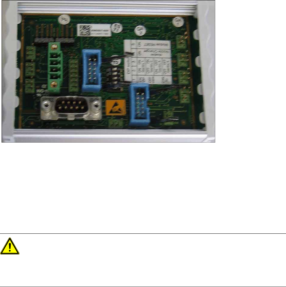
5.4 Control Unit on Tape Cutter (CAN Node Module)
With the CAN node module, a new controller [03052927-xx] has been developed for the SIPLACE X4I,
HF, D3 and X series machines. This controls both the cutter and the nozzle changer of the respective
location. If this control unit is installed in older machines, you will also need to use the relevant CAN bus
address jumper for your machine's installation site.
03079950-xx Retrofit kit CAN nodes for CPP head
4 x 03052927-xx CAN nodes NC tape cutter X/HF
4 x 03053225-xx Cable feed-in device X series: NC CAN nodes (2x flat ribbon cable)
4 x 03053223-xx Cable feed-in device for X series: nozzle station
4 x 03053229-xx Cable feed-in device X series: reject bin
4 x 03047464-xx Cable: power for CAN nodes NC/TC
40 x 00805140-xx Cable binder W=2.4 mm L=92 mm TYB-23M
80 x 00805142-xx Cable binder W=4.8 mm L=186 mm TYB-25M
40 x 00805143-xx Cable binder W=4.8.mm L=360.mm TYB-28M
1 x 00196678-xx Retrofit instructions CAN nodes for X series SW70x
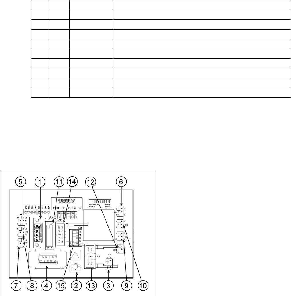
CAN node NC tape cutter module
1. X1 – Energy supply with automatic CAN ID
2. X2 – Energy supply, tape cutter +24 V/+5 V
3. X3 – Reject container (nozzles, components)
4. X4 – CAN bus connection
5. X5 – Energy supply to valve (left)
6. X6 – Energy supply to valve (right)
7. X7 – Proximity switch for stroke cylinder out
(left)
8. X8 – Proximity switch for stroke cylinder in
(left)
9. X9 – Proximity switch for stroke cylinder out
(right)
10. X10 – Proximity switch for stroke cylinder in
(right)
11. X11– Test connector, tape cutter
12. X12 – Compressed air valve (additional
pneumatic unit for rejecting components)
13. X13 – Nozzle changer, row 1
14. X14 – Nozzle changer, row 2
15. DIP switch group S3 (see below)
Overview
Control Unit on Tape Cutter (CAN Node Module) Description of CAN Node LEDs
44 Retrofit Instructions CAN Node X Series SW70x
Description of CAN node NC tape cutter module
This board is backwards compatible to the old tape cutter board. It can be used at X, HF and D series
machines.
The CAN processor decides which functions need to be checked at the individual locations, depending
on the cables connected and the type of DIP switched set.
1)
Not all gantries may be available, depending on the machine type.
2)
Even if there is no nozzle changer installed and only the tape cutter needs to be controlled, this switch
still needs to be set to OFF for the reject bin query and the reject station.
X series machine with CAN node
The cable of the machine (cable harness machine) has to be by-passed as shown in the list:
*112: Gantry 1: 10/11/12 by-passed
*122: Gantry 2: 11/12 by-passed
*132: Gantry 3: 10/12 by-passed
*142: Gantry 4: not by-passed
5.4.1 Description of CAN Node LEDs
DIP
switch
DIP switch meaning
1ON: Setting the CAN ID via DIP switch 2 and 3 – OFF: Cable Select
2 CAN - ID 0
ON: Gantry 1
1)
ON
OFF: Gantry 2
1)
ON
ON: Gantry 3
1)
OFF
OFF: Gantry 4
1)
OFF: Cable select
3 CAN - ID 1
4
ON: Only tape cutter – OFF: Nozzle changer and tape cutter
2)
5ON: Module in reset-mode – OFF: Module in standard mode
DIP switch group S3 - overview
LED Function
V39 Component reject bin
V45 Nozzle reject bin
V41 CPU green status LED
V43 CPU red status LED
V44 NC1 light barrier 24V
V42 NC1 valve active
V40 NC2 light barrier 24V
V38 NC2 valve active