00196678-0102_RI_CAN-Knoten_X-Serie70x_De EN - 第47页
Installation Replacing the Tape Cutter Control Board with the CAN Nodes Retrofit Instructions CAN Node X Series SW70x 47 X Also connect the following cable from th e retrofitting kit to the CAN nodes. 6-3: Disconnected c…
Installation
Replacing the Tape Cutter Control Board with the CAN Nodes
46 Retrofit Instructions CAN Node X Series SW70x
6.2 Replacing the Tape Cutter Control Board with the CAN Nodes
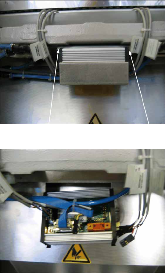
6-1: Dismantling the tape cutter control board, old
X Loosen the old tape cutter control board with
the mounting rail from the tape cutter (2
screws). You can now remove the cover on the
old control board.
6-2: Disconnecting the cable from the tape cutter control board
X Disconnect all cables from the old tape cutter
controller.
Installation
Replacing the Tape Cutter Control Board with the CAN Nodes
Retrofit Instructions CAN Node X Series SW70x
47
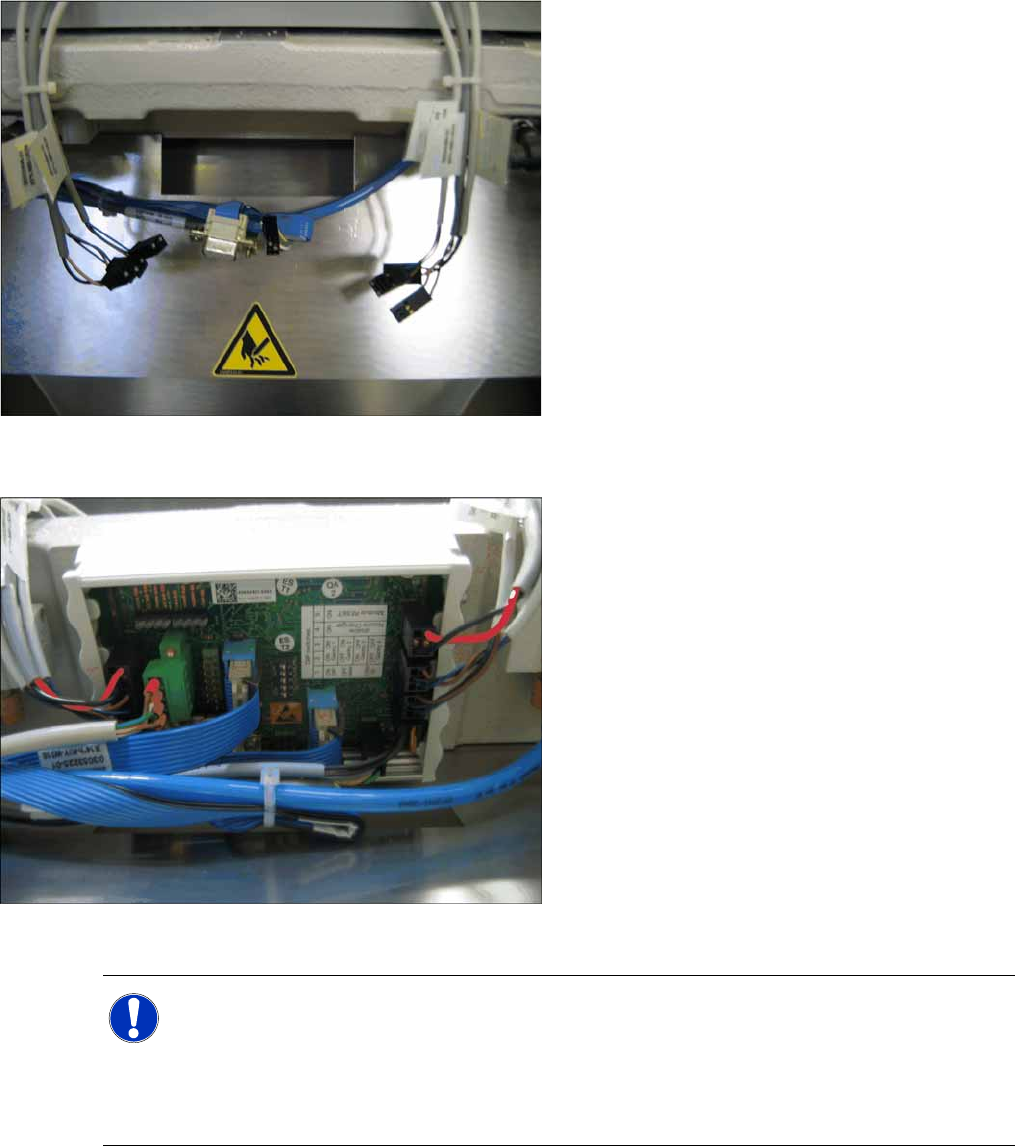
X Also connect the following cable from the retrofitting kit to the CAN nodes.
6-3: Disconnected cable on tape cutter
6-4: Connecting the cable to the fitted CAN nodes
X Disconnect the old tape cutter control board
from the mounting rail and fix this mounting rail
to the tape cutter frame.
X Connect the new CAN nodes unit to the
mounting rail. This unit is supplied with a cover
which can be also be removed once the unit
has been fitted.
X Reconnect all cables. The connections are
identical to those for the old control unit.
(connectors and contacts are labelled and
coded).
NOTE:
From SW70x, the nozzle changer and nozzle station can only be addressed via the CAN nodes.
The 1 wire is then only used for the temperature sensors on the head board.
Switch 4 on the DIP switch needs to be set to OFF: (= the nozzle changer and the tape cutter)
stand still.
See also CAN nodes. (5.4 Control Unit on Tape Cutter (CAN Node Module)
J
43)
Installation
Replacing the Tape Cutter Control Board with the CAN Nodes
48 Retrofit Instructions CAN Node X Series SW70x
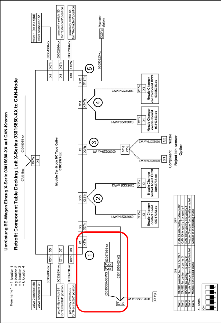
6-5: Circuit diagram for tape cutter component feed-in device with CAN nodes