00196678-0102_RI_CAN-Knoten_X-Serie70x_De EN - 第58页
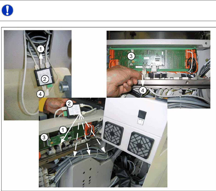
Installation Removing the 1 Wire Infrastructure 58 Retrofit Instructions CAN Node X Series SW70x 6.4 Removing the 1 Wire Infrastructure 6-17: Switching over the 1 wire cable X If the CAN nodes are retrofitted, the 1 wire…
Installation
Running the CAN Nodes Option Cable
Retrofit Instructions CAN Node X Series SW70x
57
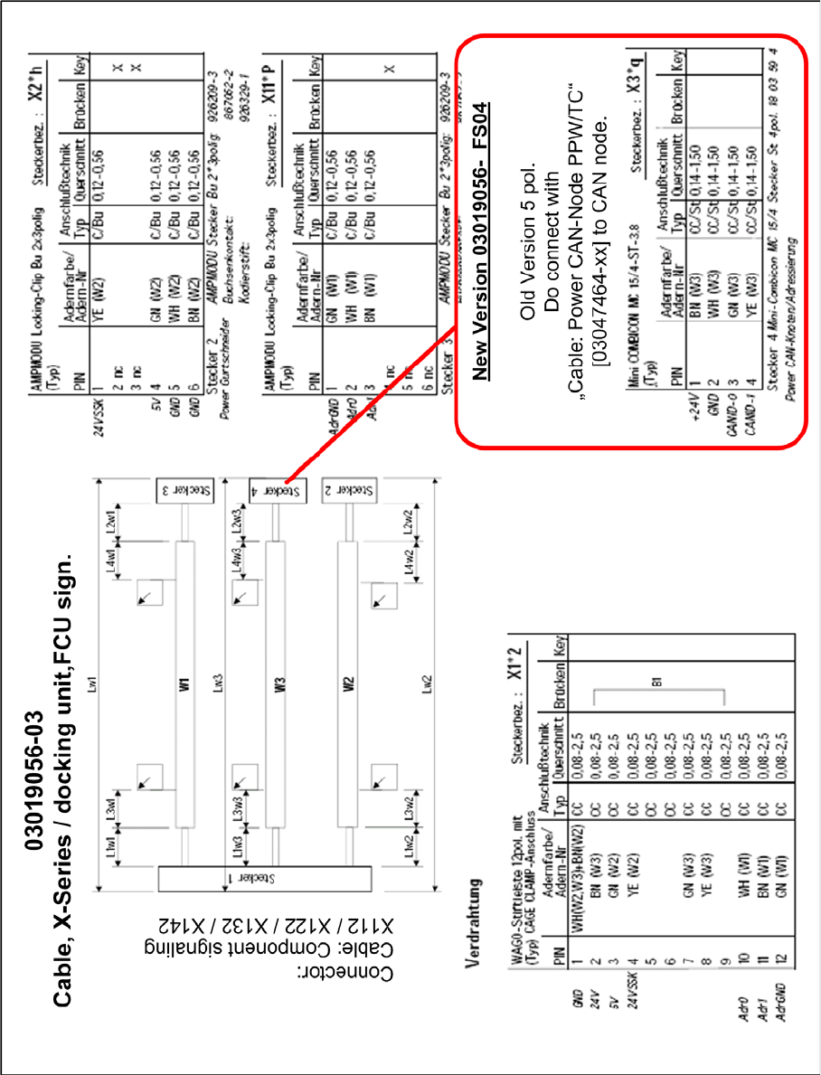
6-16: Cable for component trolley feed-in device (X series) - FCU signalling [03019056-03]
Installation
Removing the 1 Wire Infrastructure
58 Retrofit Instructions CAN Node X Series SW70x
6.4 Removing the 1 Wire Infrastructure
6-17: Switching over the 1 wire cable
X If the CAN nodes are retrofitted, the 1 wire distributor must be removed from the machine.
X To do this, remove the box PC unit from location 2 and the component trolley feed-in device FCU
power supply from location 4.
X Remove the existing CAT5 cable (4) from the I/O module (3) in the sub/main distributor. 1-Wire-
CAT5 IN connector X5 at the 1-Wire-CAT5-Distributor [03040219-xx] SPLITTER.
X The CAT5 cable [03042347-xx bzw. 03041629-xx] for the temperature sensors (1) then needs to be
unplugged from the 1 wire distributor (2) (SPLITTER connector X3) and reconnected to the I/O
module (3) in the sub/main distributor.
lay the cable as shown in the picture "switching over the 1-Wire-cable" shown through the machine
base.
X Now remove the 1 wire CAT5 distributor (2), (SPLITTER) with all connected cables, from the
machine. The power supply (green connector) isn't used any more and can stay inside the machine.
NOTE:
The 1 wire bus is still used for the temperature sensor.
(1) Patch cable [03041629-xx] to 1 wire CAT5
gantry [03042214-xx]
(2) 1 wire CAT5 distributor [03040219-xx]
(3) Interface 1 wire CAT5 [03041578-xx] to CAN I/
O module [00355051-xx]
(4) old CAT5 cable at Interface 1-Wire-CAT5 -
CAN-E/A-Module
Installation
Removing the 1 Wire Infrastructure
Retrofit Instructions CAN Node X Series SW70x
59
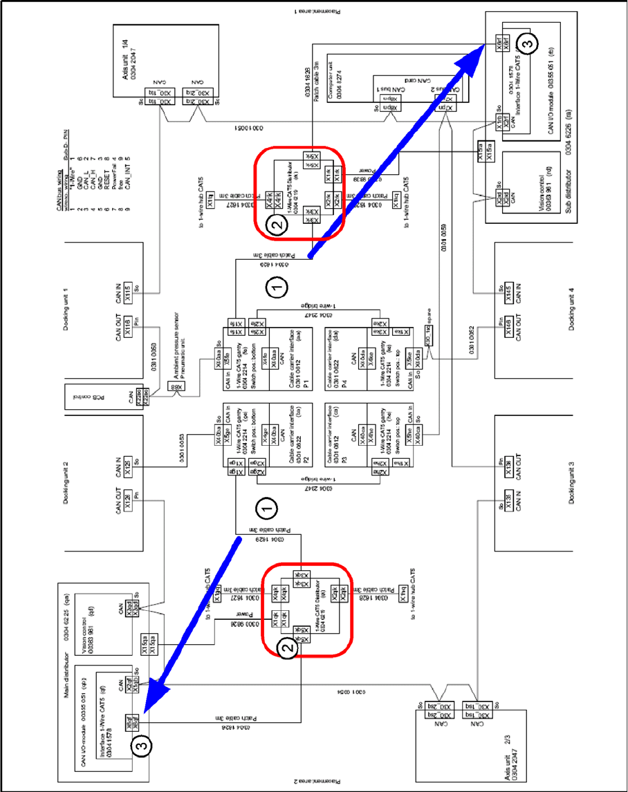
6-18: 1 wire distributor