00196678-0102_RI_CAN-Knoten_X-Serie70x_De EN - 第59页
Installation Removing the 1 Wire Infrastructure Retrofit Instructions CAN Node X Series SW70x 59 6-18: 1 wire distributor
Installation
Removing the 1 Wire Infrastructure
58 Retrofit Instructions CAN Node X Series SW70x
6.4 Removing the 1 Wire Infrastructure
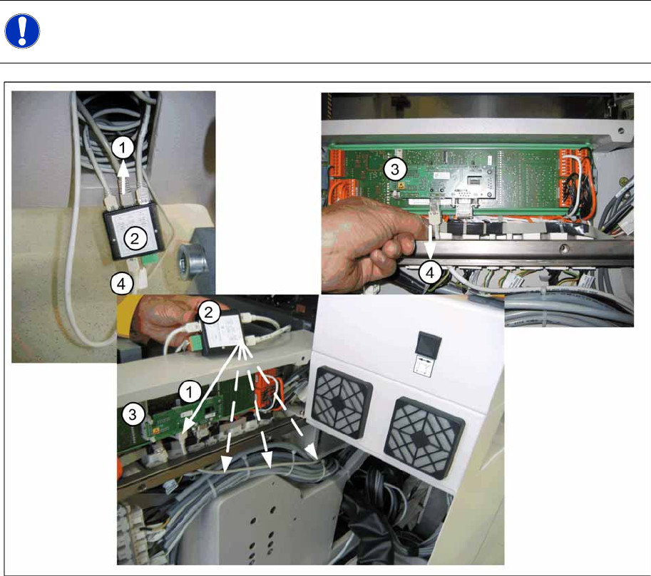
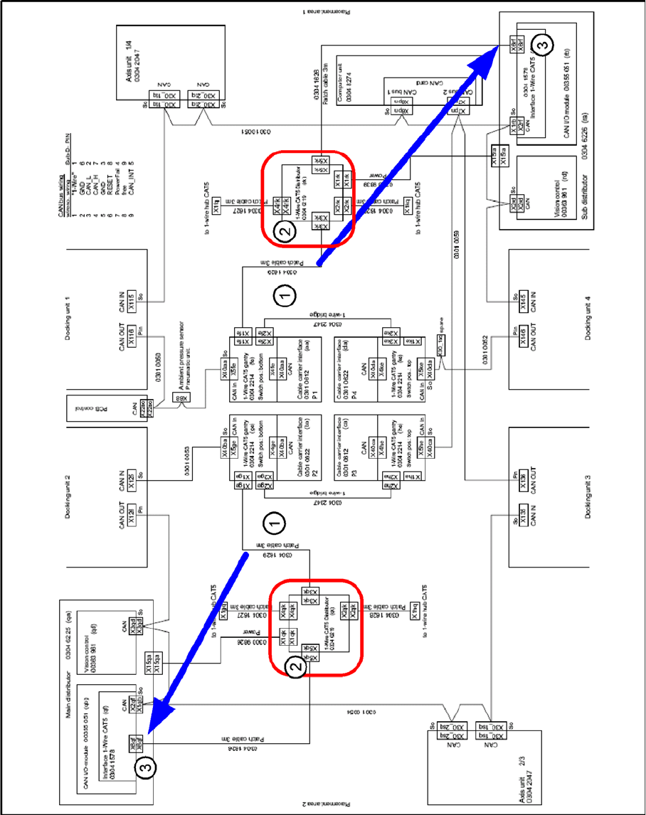
6-17: Switching over the 1 wire cable
X If the CAN nodes are retrofitted, the 1 wire distributor must be removed from the machine.
X To do this, remove the box PC unit from location 2 and the component trolley feed-in device FCU
power supply from location 4.
X Remove the existing CAT5 cable (4) from the I/O module (3) in the sub/main distributor. 1-Wire-
CAT5 IN connector X5 at the 1-Wire-CAT5-Distributor [03040219-xx] SPLITTER.
X The CAT5 cable [03042347-xx bzw. 03041629-xx] for the temperature sensors (1) then needs to be
unplugged from the 1 wire distributor (2) (SPLITTER connector X3) and reconnected to the I/O
module (3) in the sub/main distributor.
lay the cable as shown in the picture "switching over the 1-Wire-cable" shown through the machine
base.
X Now remove the 1 wire CAT5 distributor (2), (SPLITTER) with all connected cables, from the
machine. The power supply (green connector) isn't used any more and can stay inside the machine.
NOTE:
The 1 wire bus is still used for the temperature sensor.
(1) Patch cable [03041629-xx] to 1 wire CAT5
gantry [03042214-xx]
(2) 1 wire CAT5 distributor [03040219-xx]
(3) Interface 1 wire CAT5 [03041578-xx] to CAN I/
O module [00355051-xx]
(4) old CAT5 cable at Interface 1-Wire-CAT5 -
CAN-E/A-Module
Installation
Removing the 1 Wire Infrastructure
Retrofit Instructions CAN Node X Series SW70x
59
6-18: 1 wire distributor
Installation
Removing the 1 Wire Infrastructure
60 Retrofit Instructions CAN Node X Series SW70x
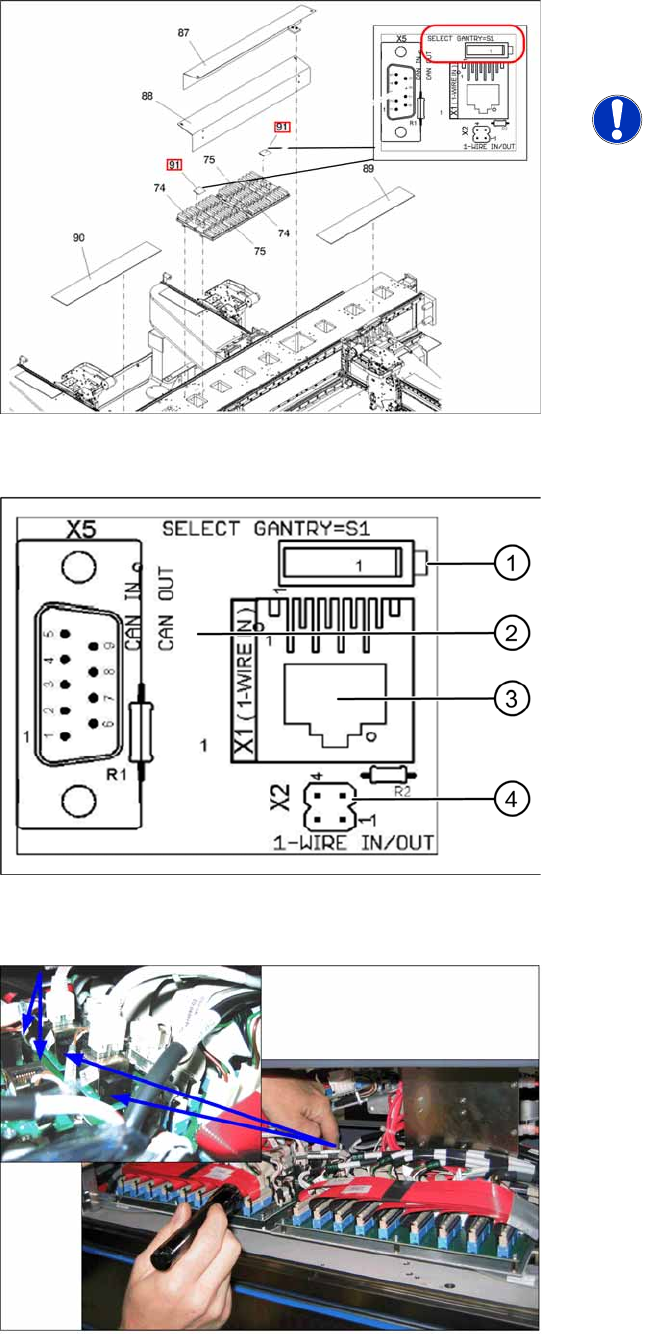
6-19: 1 wire CAT5 gantry IGUS board [03042214-xx]
X For each placement area, switch over the S1
switch on the 1 wire CAT5 gantry IGUS. (Also
see next diagram).
NOTE:
If this switch is not switched over, the
temperature correction values will be
calculated for the wrong gantry, which
can lead to placement inaccuracies
and which will show temperature error
messages for the wrong gantry.
6-20: 1 wire CAT5 gantry board [03042214-xx]
One wire CAT5 gantry board
1. Switch:
Setting for 1 wire:
Position down = gantry 1/2,
Position up = gantry 3/4
Setting for CAN nodes:
Position up = gantry 1/2,
Position down = gantry 3/4
2. This board is located directly on the CAN bus
connector of the trailing interface.
3. Connection CAT5 cable from one wire CAT5
distributor
4. X2 connection to second gantry in placement
area.
6-21: Switching over the switch for the 1 wire CAT5 interface board