00196678-0102_RI_CAN-Knoten_X-Serie70x_De EN - 第62页
Installation Converting the C&P20 Nozzle Station Dismantli ng the Nozzle Station 1 Wire Hub Valve 62 Retrofit Instructions CAN Node X Series SW70x 6.6 Converting the C&P20 Nozzle S t ation 6.6.1 Dismantling the N…
Installation
CAN Node Conversion on C&P20 Nozzle Changer
Retrofit Instructions CAN Node X Series SW70x
61
6.5 CAN Node Conversion on C&P20 Nozzle Changer
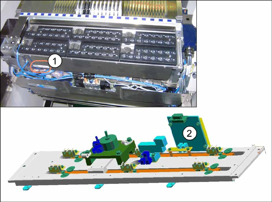
6-22: Conversion C&P20 nozzle changer
X Check the function state (FS) of the nozzle changer. This must be higher than FS03. If this is not the
case, remove the nozzle changer. Also remove the cover sheet and replace the 1 wire NC C&P20
board [03015388-xx] with a CAN-NC C&P20 board [03045735-xx]. Perform this check for all C&P20
nozzle changers used in the machine and replace them where necessary.
(1) Position of nozzle changer item number (2) CAN NC C&P20 board [03045735-xx]
Installation
Converting the C&P20 Nozzle Station Dismantling the Nozzle Station 1 Wire Hub Valve
62 Retrofit Instructions CAN Node X Series SW70x
6.6 Converting the C&P20 Nozzle Station
6.6.1 Dismantling the Nozzle Station 1 Wire Hub Valve
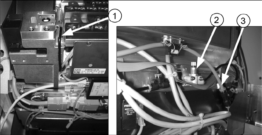
6-23: Running the hose to the nozzle station [03045404-xx]
X Disconnect the T-piece from the pneumatic supply (3).
X Remove the T-piece for the nozzle station from the component trolley feed-in device.
X Dismantle the fine throttle (2).
X Disconnect the hose (1) from the nozzle station.
X Close the open outlet of the T-piece with a dummy plug.
(1) Hose for nozzle station (2) Fine throttle
(3) T-piece
Installation
Installing the Solenoid Valve for the Nozzle Station CAN Nodes Converting the C&P20 Nozzle Station
Retrofit Instructions CAN Node X Series SW70x
63
6.6.2 Installing the Solenoid Valve for the Nozzle Station CAN Nodes
Assembly kit: "Hose for nozzle station with valve" [03051467-xx]
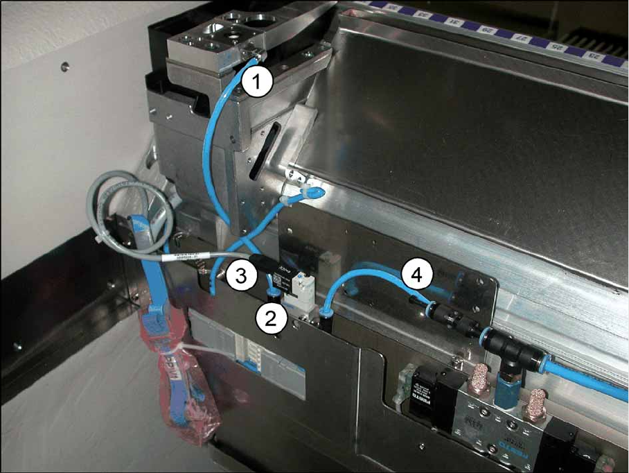
6-24: Hose for nozzle station with valve [03051467-xx]
X Install the solenoid valve (2) with the two DIN912-M3x16-A2-70 screws to the component trolley
feed-in device. If the required holes are not present, fix the solenoid valve and the hose to the
component trolley feed-in device with cable ties, after completing the work to be performed.
X Replace, unless already performed, the QSC-6H plug at the solenoid valve feed-in control with the
Y connector (4).
X Connect the "hose PUN4 125 mm" with the Y connector (4) and the solenoid valve (2). The second
opening on the Y press-fit connection needs to be connected with the pneumatic hose of the nozzle
changer or closed with the QSC-4H plug.
X Connect the hose (1) with the solenoid valve (2) and the nozzle station.
X Connect the cable which has already been connected in the component trolley feed-in device (3) to
the solenoid valve (2).
X As shown in the diagram above, fix the solenoid valve (2) with two screws (DIN 7991-M4x20-8.8) to
the component trolley feed-in device.
(1) Hose for nozzle station PUN4 200 mm (2) Solenoid valve assembly for nozzle station
[03055785-xx]
(3) Cable of feed-in device for X series [03053223-
xx]
(4) "Y connector with sleeve QSY-6H-4"
[03055792-xx]