00198574-01_Process_Foundation_DEK_Micron_EN - 第17页
4 Process Hardware 4.2 Tooling Process Foundation DEK Micron-Series 12/2017 17 Customised Tooling ● For one off applications ● Expensive ● Inflexible… 4.2.2 Correct Set Up ● Label tooling clearly to prevent mix-ups ● Too…
4 Process Hardware
4.2 Tooling
16 Process Foundation DEK Micron-Series 12/2017
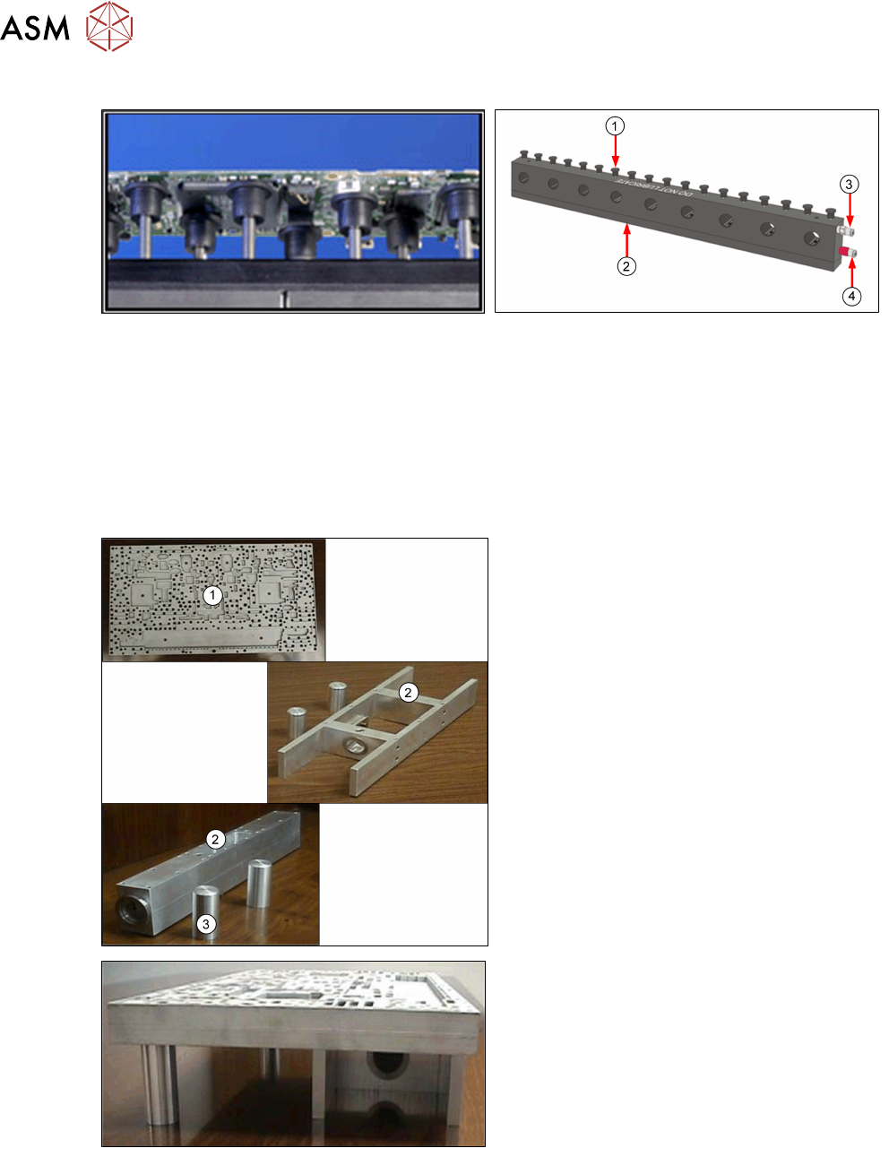
Gridlok
TM
●
Board; components and stencil support
●
Eliminates operator influence
●
Quick changeover
●
Expandable from 38-508mm board widths
●
Good for 0.6mm and thicker
●
No vacuum option…
1. Tooling Pins
2. Magnetic Base
3. Pneumatic Input to Lock Pins
4. Pneumatic Input to Raise Pins
Dedicated Tooling
1. Plate
2. Towers
3. Support Pins
●
Up to 100% support
●
Quick and accurate changeover
●
Can contain milled out areas for underside
components
●
Can be fitted with vacuum cups
●
Less expensive than custom tooling
●
One plate per product…
4 Process Hardware
4.2 Tooling
Process Foundation DEK Micron-Series 12/2017 17
Customised Tooling
●
For one off applications
●
Expensive
●
Inflexible…
4.2.2 Correct Set Up
●
Label tooling clearly to prevent mix-ups
●
Tooling blocks should make use of the locating dowels on the rising table to ensure
repeatability of positioning
●
To aid in the positioning of magnetic pins, create tooling maps or templates that can be laid on
the table surface with holes cut for the pins to go through
●
Use tooling blocks designed with stencil support, or stencil support blocks if squeegee length
exceeds board length
Care and Maintenance
●
Keep tooling and rising table scrupulously clean
●
Inspect tooling regularly for wear or damage
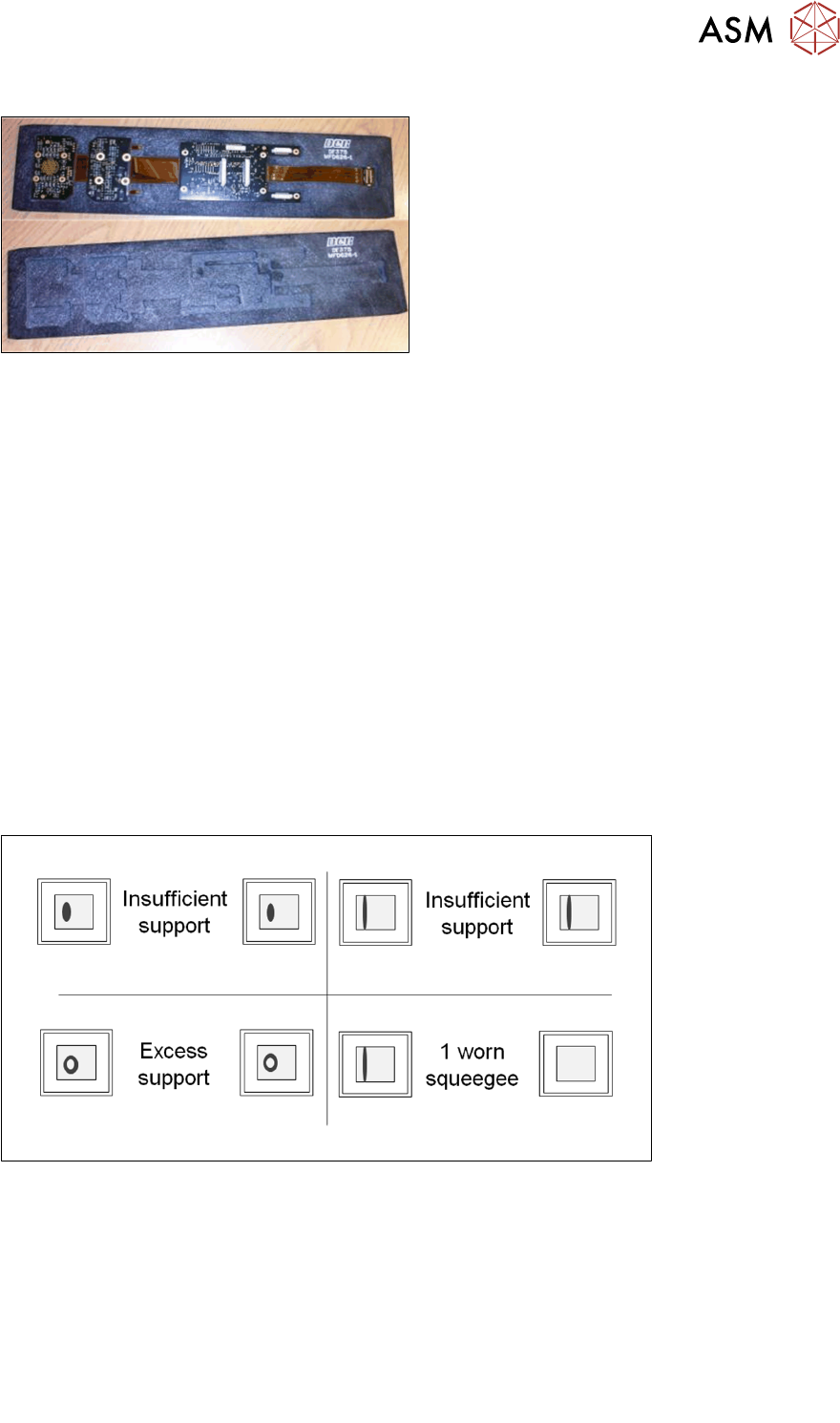
4.2.3 Identifying Tooling Problems
With everything set correctly, the stencil surface should be clean at the end of the print stroke.
Therefore, any material residues left can provide clues to underlying problems.
These problems can be caused by:
●
Damage or contamination of tooling or rising table
●
Tooling pins positioned beneath underside components
●
Tooling positioned directly under meath bar code labels, silkscreen mask or uneven pad finish
on the underside of the board
●
Worn or damaged transport belts
●
Underside components fouling on the surface of the tooling plate
Note: Adjusting the "Board Stop X" parameter slightly may allow the board to locate accurately
within the tooling block.
4 Process Hardware
4.3 Stencil
18 Process Foundation DEK Micron-Series 12/2017
4.3 Stencil
The stencil defines the volume and shape of the deposit, and the importance of a well-maintained
stencil cannot be over-emphasised. A good stencil will give high and predictable yields, will
minimise the need to clean and hence increase throughput, and reduce both downtime and
consumables use. A damaged or worn stencil may dramatically reduce yields and demand
constant cleaning and inspection, adding considerable costs to the manufacturing process. A poor
stencil, once identified, should be replaced immediately as the cost of replacement is negligible in
relation to lost production.
Good Stencil (Well designed/ good condition)
●
Excellent Results
●
Few Failures
●
Predictable Yields
Bad Stencil (Poor design/ damaged)
●
Lots of stencil wiping/ cleaning
●
Lots of bridging and open circuits
Stencil Condition
Cleanliness – Screen Wash Machine
●
Dirty apertures are one of the main causes of process defects
●
Stencils should be cleaned thoroughly in an automatic washing
machine prior to storage and possibly even at shift change
●
Remember that the under-screen cleaner supplied with the machine
is for regular, small cleaning only and cannot clean the top surface
Cleanliness – Manual
●
For manual cleaning, use a lint-free cloth. Solvent-soaked cloth in
each hand, clean both sides simultaneously
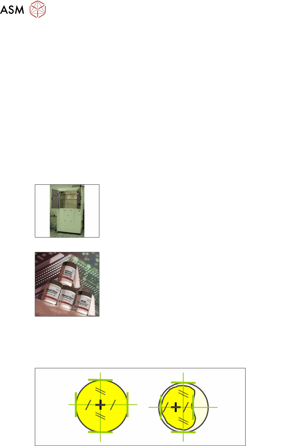
Fiducial Condition
●
The condition of the fiducials has a direct bearing on the alignment repeatability and accuracy
●
Any misalignment can cause bridging and stencil smear and increase the frequency of under-
screen cleaning
●
The stencil should be inspected regularly and damaged fiducials repaired